
Installation Instructions

34
|
NMEA2000 / SimNet | NSS Installation Manual
Planning and installing a SimNet backbone
Plan the SimNet backbone carefully
Note: For part numbers refer to ‘SimNet Accessories’ page “Simnet Cables” on page 60
The SimNet backbone needs to run between the locations of all SimNet products you want to
install, and be less than a 5.5 m (18 ft) cable run from a SimNet device.
Choose from the following components to make up your SimNet backbone:
• SimNet cables: 0.3 m (1 ft), 2 m (6,6 ft), 5 m (16.6 ft), and 10 m (33 ft) cables
• SimNet power cables with or without termination
• SimNet in-line joiner with or without termination
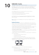
• T-Joiner. Use at locations where you want to connect a single SimNet device or join lengths of
SimNet cable
• 7 way joiner. Use to connect up to 5 devices at one location
• Wind transducer. If using a wind sensor, plan to connect this to one end of the backbone as
this has a terminator built in
Power the SimNet network
A SimNet network requires its own 12 V DC power supply protected by a 5 amp fuse or
breaker. For 24 V use a DC-DC converter
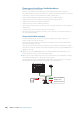
Connect power at any location in the backbone for smaller systems using a SimNet power
cable with termination (red cap).
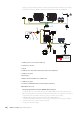
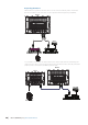
For larger systems introduce power at central point in the backbone to “balance” the voltage
drop of the network. Use SimNet cable without termination (yellow cap, part # 24005910). See
diagram on page 36.
If joining to an existing NMEA2000 network or similar CAN bus network that has it’s own
power supply, do not connect to another power supply.
Do not connect the SimNet power cable to the same terminals as the start batteries, Autopi-
lot Computer, Radar, thruster or other high current products
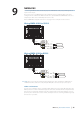
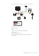
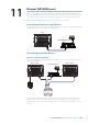
The drawing below shows a small SimNet network. Power is introduced at one end using a
SimNet power cable with termination ending with a second terminator.
12 V DC
T
T
Mico-C to SimNet
SimNet power
SimNet terminator
-
+