
Installation Instructions

36
|
NMEA2000 / SimNet | NSS Installation Manual
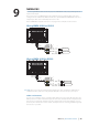
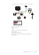
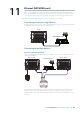
For larger systems introduce power at central point in the backbone to “balance” the voltage
drop of the network. Use SimNet cable without termination (yellow cap) (24005910)
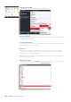
Menu
Menu
Menu
T
T
T
+
_
12 V DC
1
2
3
8
8
8
9
9
5
5
4
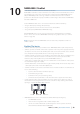
SimNet backbone
SimNet power cable
SimNet Terminator
SimNet drop cable
10
7
6
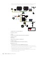
1 SimNet power source. Stable 12 V DC only
2 5 Amp fuse or breaker
3 Switch
4 SimNet power cable without termination (yellow disc) (24005910)
5 SimNet 7 way joiner
6 NSS Display
7 OP40 Controller with Micro-C to SimNet cable
8 SimNet 3 way joiner
9 Terminator (SimNet Wind Vane includes built-in terminator)
10 NSO Marine Processor
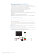
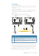
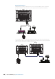
Integrating SimNet and other NMEA 2000 networks
Increasingly there are vessels that will have other NMEA 2000 based networks provided by
di erent manufacturers. If networks from di erent manufacturers are required to share data, it
is important to plan how both networks are going to interface to each other.
All NMEA 2000 compliant networks follow the same NMEA 2000 rules:
• a continuous backbone with devices connecting by a drop cable no more than 6 m (20 ft)
• two terminators, one at each end of the network
• a single 12 V DC power supply