
Installation Instructions


|
11
Planning the installation | NSS Installation Manual
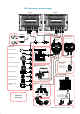
Check the contents
2
3
4
5
5
6
7
8
910
2
1
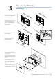
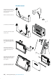
Key Description Key Description
1 Sun Cover 6 Mounting bracket (NSS7 & NSS8 only, option
for NSS12)
2 Cosmetic screw covers (x2) 7 Bracket mount rear bezel (NSS7 & NSS8 only,
option for NSS12)
3 NSS Display 8 Power cable
4 Flush mount gasget 9 Flush mount machine screws (x4)
5 Bracket knobs (x2 - NSS7 &
NSS8 only, option for NSS12)
10 Bracket mount rear bezel securing screws (x4 -
NSS7 & NSS8 only, option for NSS12)
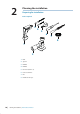
Mounting location
Choose the mounting locations carefully before you drill or cut. The display should be
mounted so that the operator can easily use the controls and clearly see the display screen.
Be sure to leave a direct path for all of the cables. Simrad displays are high-contrast and
anti-re ective, and are viewable in direct sunlight, but for best results install the display out
of direct sunlight. The chosen location should have minimal glare from windows or bright
objects.
The enclosure that the display is mounted in should be dry and well ventilated. The ventila-
tion of the space behind the unit should be enough to prevent excessive heat build up as a
combined result of radiated heat o the heat sink, and sunlight heating of the enclosure. In
very small enclosures, also subject to heating from the sun, it may be required to t forced
cooling.
Ensure that any holes cut are in a safe position and will not weaken the boat’s structure. If in
doubt, consult a quali ed boat builder.
Before cutting a hole in a panel, make sure that there are no hidden electrical wires or other
parts behind the panel.
Do not mount any part where it can be used as a hand hold, where it might be submerged, or
where it will interfere with the operation, launching or retrieving of the boat.
NSS_IM_EN_988-10107-003.indd 11 20/08/2013 4:55:19 p.m.