
Installation Instructions


12
|
Planning the installation | NSS Installation Manual
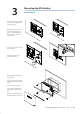
If bracket mounting the display choose an area where the display will not be subjected to
excessive vibration.
The mounting location will a ect the internal GPS receiver. Ensure you test the unit in its
intended location to ensure satisfactory reception. An external GPS source may be added to
overcome poor reception areas.
Leave su cient clearance space to connect all relevant cables.
For overall width and height requirements, please see the dimensions section on page 52.
Note: The bracket kit is an optional accessory that needs to be ordered seperately.
!
Warning: Poor ventilation combined with a small mounting enclosure could poten-
tially cause the display to overheat - B&G displays are designed to operate in temperatures
from -15° C to +55° C (+5° F to +131° F).
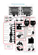
Ensure unit is not installed too close to devices that may emit harmful interference, or devices
that may be sensitive to any electromagnetic eld disruption caused by the unit. Typical
minimum ‘safe’ distances are indicated below.
2.0 m (6.5 ft) Min
1.0 m (3 ft) Min
1.5 m (5 ft) Min
RADAR
Radio or AIS Transmitter
Compass
MARK
MOB
GOTO
PAGES
MENU
STBY
AUTO
IN
MOB
OUT
MARK
MOB
GOTO
PAGES
MENU
STBY
AUTO
IN
MOB
OUT
MARK
MOB
GOTO
PAGES
MENU
STBY
AUTO
IN
MOB
OUT
NSS_IM_EN_988-10107-003.indd 12 20/08/2013 4:55:23 p.m.