NSS7, NSS8 and NSS12 Installation Guide ENGLISH www.simrad-yachting.
Preface As Navico is continuously improving this product, we retain the right to make changes to the product at any time which may not be reflected in this version of the manual. Please contact your nearest distributor if you require any further assistance. It is the owner’s sole responsibility to install and use the instrument and transducers in a manner that will not cause accidents, personal injury or property damage. The user of this product is solely responsible for observing safe boating practices.
device, pursuant to Part 15 of the FCC rules. These limits are designed to provide reasonable protection against harmful interference in a residential installation. This equipment generates, uses and can radiate radio frequency energy and, if not installed and used in accordance with the instructions, may cause harmful interference to radio communications. However, there is no guarantee that the interference will not occur in a particular installation.
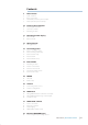
Contents 5 NSS overview 6 7 8 9 Front - Controls Rear - Connectors NSS7/NSS8 potential system example NSS12 potential system example 10 Planning the installation 10 11 11 Preparing for installation Check the contents Mounting location 13 Mounting the NSS display 13 14 Panel mount Bracket mount 15 Wiring the NSS 15 Wiring guidelines 16 Connecting power 16 16 17 18 18 Power connection (basic) Power Control (yellow wire) Power Control setup External alarm External Alarm Setup 19 External G
4| 36 38 Connecting to multiple devices Ethernet setup 39 Autopilot 39 40 41 Wiring the autopilot system Using the SG05 EVC gateway Autopilot setup 48 CZone connection to NMEA 2000 49 50 50 51 51 CZone setup Backing up user data NSS software updates NMEA 2000 and Ethernet device updates Touch Screen Calibration 52 Dimensioned Drawings 52 53 54 NSS7 NSS8 NSS12 55 Connector Pinouts 55 55 56 56 56 57 57 Power Video / Data NMEA 2000 Network (Ethernet) Echosounder NMEA 2000 cables Ethernet cabl
1 NSS overview NSS Sport Touchscreen multifunction display range includes three display sizes: 6.4” (VGA) ,8.0” (SVGA), and 12” (XGA). Ultrabright LED backlit screens are used across the range. All three models include an internal GPS antenna. The NSS12 features an internal ethernet switch with 3 ethernet connectors for extra network connectivity, whereas the NSS7 and NSS8 have built-in echosounders and a single ethernet connector.
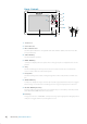
Front - Controls SIMRAD 6 5 PUS H 4 STBY AUTO TO EN TER 7 MARK MENU GOTO PAGES IN MOB OUT MOB 8 9 10 NSS 7 1 2 2 3 1 Touchscreen 2 Card reader door 3 Micro-SD Card reader Used for optional Navionics or InsightHD chart data, software updates, transfer of user data and system backup. 4 STBY / AUTO key Used for Autopilot operation. 5 MARK / MENU key A short press displays the active panel’s menu. A long press places a waypoint at the vessel’s position.
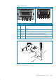
Rear - Connectors NSS12 NSS7 & NSS8 1 2 3 4 5 2 3 4 5 5 5 Key Function 1 ECHO 2 3 4 5 Description Built in Broadband Echosounder on the NSS7 and NSS8. NSS12 requires an optional echo sounder module connected via ethernet For power input 12 or 24 V DC input, Power control, and external POWER alarm.
NSS7/NSS8 potential system example NSS7 or NSS8 VIDEO /DATA POWER Black Video 2 (Green) Red (FUSE) Yellow Blue Video 1 (Red) _ + 12 or 24 V DC RX + Green Orange RX NMEA 0183 Serial port Yellow TX + Ext.
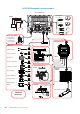
NSS12 potential system example NSS12 NSS12 VIDEO IN ETHERNET SWITCH ECHOSOUNDER BSM-1 or BSM-2 NEP-2 POWER NETWORK NMEA2000 POWER: 12 V DC HD Radar NETWORK NETWORK NETWORK NETWORK 2, 4, 6, 10 or 25 kW External GPS: ZG50 AIS: NAIS-400 TRANSDUCER Auto Pilot: Triton / AC12 BROADBAND RADAR Heading Sensor: RC42 3G/4G Various inhull, through hull, and transom mount options available Audio: SonicHub Engines: NMEA2000 IMAGING SONAR Instruments: Triton Digital Switching: CZONE WEATHER Sirius
2 Planning the installation Preparing for installation Tools required 3 4 5 6 7 8 1 2 1 Drill 2 Jig Saw 3 Drill Bit 4 Drill Bit 5 Hole Saw (25mm / 1”) 6 Pozi Screw Driver 7 File 8 PVC Electrical Tape 10 | Planning the installation | NSS Installation Manual
Check the contents 2 5 1 2 3 4 76 5 8 9 Key 1 Description Sun Cover Key 6 2 Cosmetic screw covers (x2) 7 3 4 NSS Display Flush mount gasget 8 9 5 Bracket knobs (x2 - NSS7 & NSS8 only, option for NSS12) 10 10 Description Mounting bracket (NSS7 & NSS8 only, option for NSS12) Bracket mount rear bezel (NSS7 & NSS8 only, option for NSS12) Power cable Flush mount machine screws (x4) Bracket mount rear bezel securing screws (x4 NSS7 & NSS8 only, option for NSS12) Mounting location Choose the m
If bracket mounting the display choose an area where the display will not be subjected to excessive vibration. The mounting location will affect the internal GPS receiver. Ensure you test the unit in its intended location to ensure satisfactory reception. An external GPS source may be added to overcome poor reception areas. Leave sufficient clearance space to connect all relevant cables. For overall width and height requirements, please see the dimensions section on page 52.
3 Mounting the NSS display Panel mount Attach the flush mounting template to the selected mounting position using adhesive tape. Drill pilot holes for the four hole saw cuts and four self tapping screws used to secure the display. If using M4 machine screws use a 5 mm (0.20 ”) drill bit. Use a 25 mm (1 “) hole saw to cut the four corner radius. Cut along the dotted line and remove the shaded area. Peel backing off the gasket and apply to the surface.
Bracket mount Using the bracket as a template, mark places to drill the central cable hole and four pilot holes for the bracket fasteners. Drill cable and fastener pilot holes. screw bracket down with fasteners. Fit rear bezel to NSS using supplied machine screws. Align the NSS ratchet teeth with those of the bracket and partially screw in the bracket knobs one at a time. Further tighten both knobs to ensure the unit is held securely and can’t tilt forward under it’s own weight.
4 Wiring the NSS Wiring guidelines Don’t do this Do this Don’t make sharp bends in the cables Do make drip and service loops Don’t run cables in a way that allows water to Do tie-wrap all cables to keep them secure flow down into the connectors Don’t route the data cables in areas adjacent If cables are shortened, lengthened, or reto radar, transmitter, or large current carrying terminated, do insulate and protect all wiring cables connections Do leave room at the back to install and remove cables ! W
5 Connecting power Power connection (basic) The NSS display can be powered by either 12 V or 24 V DC. Displays are protected against reverse polarity, under voltage and over voltage.
Power Control Master Power Control Slave A B Black Red C Black Red Yellow Yellow Broadband Radar Black Red Yellow + _ 12 - 24 V DC Power Control Bus Power Control Master Display (A) turns on using the power button. It is set as the Power Control Master and will output voltage on the Power Control bus to turn on display (B) and Broadband radar (C).
External alarm Blue wire on power cable: An external alarm can be connected to one or more displays on the network. The external alarm can be a small peizo buzzer connected directly, or a horn siren connected via a relay. Alarms are configured globally in the system i.e they can be configured on one display and seen, heard and acknowledged from all displays. How ever the external alarm siren can be enabled or disabled on individual displays.
6 External GPS Mounting location Depending on vessel design and materials, certain mounting locations chosen for the NSS may not offer adequate GPS satellite signal reception using the internal receiver. An external GPS source such as the GS15 can be used to overcome this, by allowing remote installation in a location that has an unobscured view of the sky. An NMEA 2000 expansion kit may be required to connect the GPS antenna to the NSS, if no other network cabling is already installed.
7 Echosounder Internal echosounder The NSS7 and NSS8 have an Internal Broadband Echosounder. Navico transducers fitted with the 7 pin blue connector can be plugged directly into the corresponding blue socket adjacent to the power connector. External echosounder An optional Navico external sounder module (eg. BSM-1, BSM-2, StuctureScan HD) can be added to the NSS7, NSS8 and NSS12 via the ethernet port on any of these devices.
Transducer adapter cables For vessels with existing transducers that do not have the Navico blue 7 pin connector, there are two adapter cables available to assist with installation. For vessels that already have a transducer that was used with older Navico products that has 6 pin connector. Use 000-00022-001 6 pin to 7 pin transducer adapter cable. These transducers will require the 10 k temp version of the transducer selected for transducer type in Echo Installation.
Echosounder setup Select echosounder source Choose the Echosounder source in the Echo Settings . MENU > MENU > ECHO. This can be selected to be the echosounder built in to the display (NSS7 and NSS8 only), or an external sounder module such as the BSM-1. Deselecting the Network Echosounder option, limits source selection to internal sonar only.
ment, divide the SOG by the paddlewheel speed, and multiply the product by 100. Calibration range: 50-100%. Default is 100%. Water speed averaging (echosounder transducer) Averages water speed by measuring your speed at a selected interval of time. Water speed intervals range from one to thirty seconds, e.g. If you select five seconds, your displayed water speed will be based on averaging over 5 seconds of sampling. Calibration range: 1-30 seconds. Default is 1 second.
8 RADAR Broadband radar (3G / 4G) 2 1 3 Micro-C Ethernet 4 5 6 FUSE 8 FUSE 10 97 7 Magnetic heading source required for Chart overlay / MARPA FUSE _ + 12 Network 9 Alternative: NMEA0183 heading Micro-C Micro-C to SimNet Ethernet cable Ethernet cables if using NEP-2 24 | Key Description 1 NSS display 2 BroadBand™ Radar Scanner 3 Interconnection cable 4 RI10 Radar interface box 5 6 Ethernet cable Ethernet cables 7 NEP-2 expansion port module 8 9 Micro-C drop cable Micro-C t
HD radar 2 1 Optional second NSS 3 5 4 F FUSE 7 FUSE 6 FUSE 8 FUSE Magnetic heading source required for Chart Overlay / MARPA _ + 9 Micro-C cable Ethernet cable extra ethernet cables Key Description 1 2 3 4 5 6 7 8 9 NSS Display HD radar scanner HD radar processor module Ethernet adaptor cable Ethernet cable (Navico 5 pin type) NEP-2 Expansion Port module (optional - used where extra ports are required) RC42N rate compass AT10HD (provides heading data to radar processor for radar overlay
Radar setup Setup and configuration of the Broadband radar has been simplified compared to traditional pulse radars. There is no zero range (time delay), no warm up time, and no burn-in required.. Radar status Scanner type Identifies the model of scanner connected to the network. Software version Check to make sure you have the latest software. check website for the latest version. Serial Number This number should be recorded for support and insurance purposes.
Sidelobe suppression Note: This control should only be adjusted by experienced radar users. Target loss in harbour environments may occur if this control is not adjusted correctly. Occasionally false target returns can occur adjacent to strong target returns such as large ships or container ports. This occurs because not all of the transmitted radar energy can be focused into a single beam by the radar antenna, a small amount energy is transmitted in other directions.
9 Video In Connect up to two composite video cameras to each display unit using the optional Video / Data cable. This connects to the VIDEO IN port on the rear of the display. Note: The video images will not be shared with other displays via the network. It is only possible to view video on the unit connected to the video source.
10 NMEA 0183 To exchange NME0183 data, the NSS display has a NMEA 0183 serial port, providing both an input and an output. The port uses the NMEA 0183 (serial balanced) and RS232 (single ended) standards, and can be configured in the software for different baud rates up to 38,400 baud. NMEA 0183 sentences output by the NSS can be individually turned on or off. Refer to “NMEA 0183 supported sentences” on page 61 for a complete list of sentences.
Serial port setup NMEA 0183 setup is done from the Network Settings page. Receive waypoint Select this option to allow device capable of creating and exporting waypoints via NMEA 0183 to transfer directly to the NSS. Serial communication This should be set according to correspond with devices connected to the NMEA 0183 input and output. RS422 is the default setting. The input and output always use the same standard.
NMEA 2000 / SimNet 11 Device connection All models of NSS are equiped with an NMEA 2000 port, which allows the receiving and sharing of a multitude of data from various sources. Essential network information • • • • • A NMEA 2000 network consists of a linear “backbone” from which “drop cables” connect to NMEA 2000 devices NMEA 2000 cables used for Simrad products are of the ‘micro-c’ style, which is a cable/ connector specification approved for use in NMEA 2000 certified networks.
Power the network A NMEA 2000 network requires its own 12 V DC power supply protected by a 5 amp fuse or breaker. For 24 V systems, use a DC-DC converter to supply 12 V Connect power at any location in the backbone for smaller systems. For larger systems introduce power at central point in the backbone to “balance” the voltage drop of the network. Note: If joining to an existing NMEA 2000 network or similar CAN bus network that already has it’s own power supply, do not make another power connection.
Data bridging NMEA 0183 to NMEA 2000 All supported NMEA 0183 sentences entering the system are internally bridged (converted) to NMEA 2000, and output via the NMEA 2000 port for any other devices to use. The only exception is AIS data. NMEA 2000 to NMEA 0183 The NMEA 0183 sentences shown in the ‘Transmit’ rows of the NMEA 0183 Supported Sentences table will be generated if the data is available from a NMEA 2000 data source.
NMEA 2000 / SimNet setup Setup is required on initial start up of the system, or if any part of the NMEA 2000 network has been changed or replaced.
corrected using the Advanced Source Selection. An example of this is where twin installations with NMEA 2000 compliant engines are not programmed with unique instance numbers. This means that the auto select feature can’t determine which engine is fitted on the port and which is fitted on the starboard side. Network Groups It is also possible to group certain settings so they are duplicated across the network on multiple displays.
12 Ethernet (NETWORK port) The NSS system uses an Ethernet network to interconnect high bandwidth devices such as radar, echosounder and to another NSS, NSE or NSO displays. The NSS7 and NSS8 displays have one network port each, whereas the NSS12 has three Ethernet ports. Navico Ethernet network cables have orange connectors that are retained by a bayonet type locking collar. Note: a maximum of two NSS may be connected to the same network.
Expanding the NSS12 With the NSS12, up to three ethernet devices can be connected directly to the unit. If more than three modules need connection, use the optional network expansion port (NEP-2). NSS12 BSM-1 Broadband Radar A second NSS connected to one of the NSS12’s three built in ports will have full visibilty and control over any devices connected to another port on the NSS12, in the same way it would if all devices were connected via an NEP-2 expansion port.
Ethernet setup No special setup is required for establishing an ethernet network, it is all ‘plug and play’ . An NEP-2 connected between an NSS and another network module (e.g. BSM-1) will automatically start working, and relay data between the two devices. Diagnostics The UDB (User Data Base) tab on the diagnostics page, provides information on Ethernet activity, which is presented in two tables as shown below.
Autopilot 13 The Simrad NSS includes complete autopilot integration. When an NSS is connected to a compatible Simrad Autopilot Computer (AC12, AC42, and SG05), you will have complete control, setup and integration with your autopilot. The NSS display can be used in conjunction with Simrad OP10, AP24, or AP28 Control units or the NSS can be used alone to conserve dash space.
Using the SG05 EVC gateway The SG05 is connected to the SimNet network in place of Autopilot computer. It connects to a Volvo Gateway for communication with Volvo’s EVC system. Note: rudder angle data is sourced from the EVC system and a seperate rudder angle indicator is not required.
Autopilot setup Verifying the autopilot connection When an AC12N, AC42N, or SG05 is connected to the NSS system, the NSS will automatically detect the autopilot and an Autopilot menu item will be included in the ‘Settings’ menu. If no ‘Autopilot’ item is available in the menu, establish the connection by running the auto select process. The auto select process may also be used if the list of data sources needs to be updated when a unit has been physically replaced.
accurate rudder angle indicator on the autopilot display. Unless impractical or impossible, a rudder feedback unit should be installed. 5. Set the drive voltage • Refer to the drive unit table in the AC12N/AC42N Installation manual or to your drive unit documentation for information. 6.
Note: You can switch the autopilot to standby mode and take manual control of the boat at any time during the seatrial by pressing the ‘STBY/AUTO’ key.
LUBBER LINE Magnitude of local field in % of earth’s magnetic field. Direction of local field with respect to lubber line. It can also be on the reciprocal. 1. Find the bearing from the boat position to a visible object. Use a chart or a chart plotter 2. Steer the boat so that the center line of the boat is aligned with the bearing line pointing towards the object 2. Change the offset parameter so that the bearing to the object and the compass readout becomes equal.
HI-A LO-A HI-M LO-M High response parameters set automatically Low response parameters set automatically High response parameters set manually Low response parameter set manually Autotuning The autotune feature will run the boat through several tests and then automatically set the most important steering parameters. Autotune is not required for the autopilot to function, as it is preset with steering parameters that should steer most boats in the 30-50 foot range.
Layline steering Layline steering is useful when navigating. Cross Track Error (XTE) from the navigator will keep the boat on the track line. If the XTE from the navigator exceeds 0.15 nm, the autopilot will calculate the layline and track towards the waypoint. Manually adjusting steering parameters The autotune function in the autopilot is so refined that the majority of boats will need no further adjustments of the steering parameters.
By increasing the Minimum rudder parameter you may improve the course keeping performance on some boats. This will however increase the rudder activity. Minimum wind angle to port and starboard These parameters should be set identical to the minimum apparent wind angle that will keep the sails from stalling and maintain boat speed. The parameters will vary from boat to boat. The settings are used for the tack-prevent function. They also apply when the autopilot is operating in WindNAV mode.
14 CZone connection to NMEA 2000 When interfacing to C-ZONE network it is recommended to use a BEP Network interface bridge (A) to join the two network backbones together. The CZONE / NMEA 2000 Network interface bridge isolates the power of the two networks, but allows data to be freely shared between both sides. The Network Interface has built in terminators so needs to be placed at the extremity of each network backbone.
CZone setup In order to communicate with the CZone modules connected to the network, the NSS display must be assigned a unique CZone Display Dipswitch setting. The functionality of the CZone system is determined by the CZone Config File (.zcf ), which is stored on all CZone modules and supported Simrad displays, such as the NSS. The file is created using the CZone Configuration Tool, a specialised PC application available from BEP Marine Ltd, and associated CZone distributors.
Software Updates and Screen Calibration 15 From time to time Simrad releases software updates to it’s existing products. Updates are created for a variety of reasons; to add or improve features, to add support for new external devices, or to fix software bugs. Updates can be found on the Simrad website: http://www.simrad-yachting.com/Downloads/ Software-Updates/ The NSS may be used to apply software updates to itself, and to supported NMEA 2000 and CZone devices, with files read off a Micro SD card.
to commence update. Do not remove the Micro SD card or repower the NSS until the process is completed (this will typically take no more than a couple of minutes). NMEA 2000 and Ethernet device updates To update SimNet and ethernet devices select the Upgrade option presented when the file is highlighted, followed by confirmation of the device you wish to upgrade. Do not interrupt the upgrade process. Touch Screen Calibration 1. Turn the unit off 2. Press and hold the MENU key, then turn the unit on 3.
52 | Dimensioned Drawings | NSS Installation Manual 123 mm (8.77") 229.5 mm (9.03") 260 mm (10.23") SUN COVER 234.5 mm (9.23") 26.5 mm (1.04") 140.5 mm (5.53") 69.5 mm (2.73") 120 mm (4.72") 2.3 mm (0.09") 12 mm (0.47") 212.5 mm (8.37") 67 mm (2.63") 44.5 mm (1.75") 37 mm (1.45") 88 mm (3.46") 16 Dimensioned Drawings NSS7 161 mm (6.33") 166 mm (6.53") 168.5 mm (6.
192 mm (7.56") 199 mm (7.83") 277 mm (10.90") 283.5 mm (11.16") 306.9 mm (12.08") SUN COVER 26.5 mm (1.04") 171 mm (6.73") 120 mm (4.72") 68 mm (2.67") 2.3 mm (0.09") 12 mm (0.47") 265 mm (10.43") 69 mm (2.71") 41 mm (1.61") 41 mm (1.61") 103 mm (4.05") 197 mm (7.75") 288 mm (11.
Dimensioned Drawings | NSS Installation Manual 255 mm (10.39") 250 mm (9.84") 54 | .1 347 mm (9.72") 12 375 mm (14.76") 353 mm (13.89") SUN COVER 26 mm (1.02") 231 mm (9.09") 135 mm (5.31") 2.3 mm (0.09") 83.5 mm (3.28") 12 mm (0.47") CUTOUT 337 mm (13.26") 335.5 mm (13.20") 229.5 mm (9.03") 41 mm (1.61") 54.5 mm (2.14") 75 mm (2.95") 140 mm (5.51") 357.5 mm (14.07") NSS12 265 mm (10.
17 Connector Pinouts Power Power Connector 1 4 2 3 Power Cable: 000-00129-001 (included) 2 m (6.
NMEA 2000 NMEA 2000 Connector 2 1 5 3 4 Pin 1 Function CAN_H 2 3 4 5 SimNet power (+) 12 V DC SimNet power (-) Shield CAN_L Network (Ethernet) NETWORK (Ethernet) Connector 5 4 3 1 2 Pin Function 1 TX + 2 3 4 5 TX RX + RX Gnd Echosounder Echosounder Connector 2 1 3 7 6 4 5 56 | Connector Pinouts | NSS Installation Manual Pin 1 Function Depth + 2 3 4 5 6 7 Speed Speed power Temp Depth Shield Temp / speed Gnd
18 Accessory cables NMEA 2000 cables Part Number Description 000-0124-69 NMEA 2000 STARTER KIT: 120 OHM RES FEM BLK 120 OHM RES MALE BLK N2K-T-RD T-CONNECTOR N2KEXT-2RD 2’ (0.61M) EXTENSION CABLE N2KEXT-15RD 15’ (4.55M) EXTENSION CABLE N2K-PWR-RD POWER CABLE 000-10996-001 N2K 4-WAY BLOCK MICRO -C 000-0127-52 TERMINATING RESISTOR KIT (MALE AND FEMALE) 000-0119-79 N2K-T-RD T-CONNECTOR 000-0119-75 N2K-PWR-RD POWER CABLE 000-0119-88 N2KEXT-2RD 2’ (0.61M) EXTENSION CABLE 000-0127-53 N2KEXT-6RD 6’ (1.
19 Supported data NMEA 2000 PGN List NMEA 2000 PGN (receive) 59392 59904 60928 61184 65285 65289 65291 65292 65293 65323 65325 65341 65480 126208 126992 126996 127237 127245 127250 127251 127257 127258 127488 127489 127493 127503 127504 127505 127506 127507 127508 127509 128259 128267 128275 129025 129026 129029 129033 129038 129039 129040 129283 129284 129539 58 | Supported data | NSS Installation Manual ISO Acknowledgement ISO Request ISO Address Claim Parameter Request/Command Temperature with Instan
129540 129794 129801 129802 129808 129809 129810 130074 130306 130310 130311 130312 130313 130314 130576 130577 130840 130842 130845 130850 130851 130817 130820 130831 130832 130834 130835 130838 130839 130843 GNSS Sats in View AIS Class A Static and Voyage Related Data AIS Addressed Safety Related Message AIS Safety Related Broadcast Message DSC Call Information AIS Class B “CS” Static Data Report, Part A AIS Class B “CS” Static Data Report, Part B Route and WP Service - WP List - WP Name & Position Wind
NMEA 2000 PGN (transmit) 61184 65287 65289 65290 65291 65292 65293 126208 126992 126996 127237 127250 127258 128259 128267 128275 129025 129026 129029 129283 129284 129285 129539 129540 130074 130306 130310 130311 130312 130577 130840 130845 130850 130818 130819 130828 130831 130835 130836 130837 130839 130845 130850 60 | Supported data | NSS Installation Manual Parameter Request/Command Configure Temperature INSOcts Trim Tab Insect Calibration Paddle Wheel Speed Configuration Backlight Control Clear Flu
NMEA 0183 supported sentences TX / RX GPS Receive GGA GLL GSA GSV VTG ZDA Transmit GGA GLL GSA GSV VTG ZDA APB BOD BWC BWR RMC Navigation Receive RMC Transmit AAM RMB XTE XDR Echo Receive DBT DPT MTW VLW VHW Transmit DBT DPT MTW VLW VHW HDT HDM Compass Receive HDG Transmit HDG Wind Receive MWV MWD Transmit MWV MWD AIS / DSC Receive DSC DSE VDM AIS sentences are not bridged to or from NMEA 2000.
62 | 6.4 inch VGA color TFT LCD 1200 nits Display type Display brightness Specifications | NSS Installation Manual Micro-C (1) Composite video (2) (multiplexed) Micro SD (1) NMEA 2000 Video input Data card slot 30.5 x 27.9 x 27.9 cm (12" x 11" x 11") 2.54 kg (5.6 lb) Pack dimensions (L x W x H) Pack weight 50/200 or 83/200 kHz Max 250 W peak to peak (31 W RMS) actual Sonar frequency Sonar output power Echo sounder 1.6 kg (3.
0191 N2584 *988-10107-003*