
Installation Instructions


42
|
Autopilot | NSS Installation Manual
accurate rudder angle indicator on the autopilot display. Unless impractical or impossible, a
rudder feedback unit should be installed.
5.
Set the drive voltage
• Refer to the drive unit table in the AC12N/AC42N Installation manual or to your drive unit
documentation for information.
6.
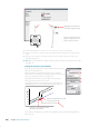
Run the rudder test as described in the on-screen instructions
Note: If the boat uses power assisted steering, it is important that the engine or electric mo-
tor used to enable the power assist steering is turned on prior to this test.
Stand CLEAR of the wheel and do not attempt to take manual control of the wheel
during this test!
• When this test is started the autopilot computer will issue a series of PORT and STBD rudder
commands and automatically verify correct rudder direction. It detects minimum power to
drive the rudder and reduces the rudder speed if it exceeds the maximum preferred speed
(8°/sec.) for autopilot operation. The system will also detect whether the drive unit is a revers-
ible motor or if a solenoid valve is operated.
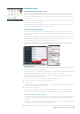
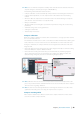
Rudder drive setup
The rudder drive setup controls how the autopilot computer controls the steering system.
Drive voltage
Voltage speci ed for your drive unit.
The Drive unit voltage setting does not apply when the system
operates solenoids on a continuous running pump/steering gear.
Hence, the output voltage to the solenoids will be the same as the
input voltage.
Refer to the drive unit table in the AC12N/AC42N Installation manual
or to your drive unit documentation for information.
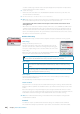
!
Warning: Selection of improper voltage level for your drive unit may damage both the
drive unit and the AC12N/AC42N even if the protection circuits are activated.
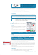
Drive engage
Clutch This is the default setting and it allows you to steer the boat with the helm or
wheel when in STBY mode (FU and NFU modes) as well as in all auto steering
modes
Auto This option is typically used to switch between two rudder speeds on a continu-
ous running pump, used when di erent rudder speeds are required for automatic
and Follow-up/Non-Follow-up steering
Motor output
Shows the amount of power needed to achieve the correct rudder speed. The reading is
obtained from the Rudder test.
The automatically set value may be increased or decreased.
Rudder deadband
This parameter is used to prevent the rudder from hunting. The reading is obtained from the
Rudder test which optimizes the deadband to the speed of the boat and the pressure on the
rudder.
If the auto-setting does not perform properly due to high inertia from the wheel or a loose
steering gear, it can be adjusted manually. Find the lowest possible value that will prevent the
rudder from continuous hunting. A wide deadband will cause inaccurate steering.
Note: The rudder deadband setting is not available when the autopilot is con gured for
Virtual Rudder Feedback.
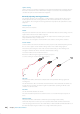
Seatrials
A seatrial can only be performed if the dockside settings are completed and con rmed.
The seatrial must always be performed in open waters at a safe distance from other tra c.
NSS_IM_EN_988-10107-003.indd 42 20/08/2013 4:56:48 p.m.