NSS Operator Manual ENGLISH www.simrad-yachting.
Preface As Navico is continuously improving this product, we retain the right to make changes to the product at any time which may not be reflected in this version of the manual. Please contact your nearest distributor if you require any further assistance. It is the owner’s sole responsibility to install and use the instrument and transducers in a manner that will not cause accidents, personal injury or property damage. The user of this product is solely responsible for observing safe boating practices.
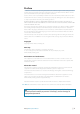
The software This manual is written for Simrad NSS Release to Market 1 (RTM1). Please check web site for details on release version. GOTO PAGES A Note: The About dialog above is an example only and may not match the sw installed on your unit! The manual will be continuously updated to match new sw releases. The latest available manual version can be downloaded from www.simrad-yachting.com.
Contents 7 Introduction 7 8 The NSS front panel and keys The NSS screen 11 Basic operation 11 11 11 12 12 13 The power key Using the touch screen Pages and panels The menus Dialog boxes Positioning a Man Over Board mark 14 Charts 14 14 14 14 15 16 16 16 17 18 19 The chart panel Chart scale Panning the chart The vessel symbol Using the cursor on the chart panel Positioning the chart on the panel Chart overlay Using 3D charts Insight chart options Navionics chart options The chart settings panel 2
38 38 39 4| Using the NSS in an AP24/AP28 system Using the autopilot in an EVC system The autopilot settings panel 42 Using the radar 42 42 42 43 43 44 45 45 47 48 49 The radar panel The radar operational modes Using the cursor on the radar panel Optimizing the radar image Positioning the radar center Measuring range and bearing to a target Setting a guard zone around your vessel Radar options MARPA targets Radar overlay Radar settings panel 50 The echosounder 50 51 52 52 53 53 53 53 54 55 55 Sett
66 67 67 68 Operating the audio source Audio playback Using the FM/AM radio Using Sirius radio 69 SiriusXM™ weather (North America only) 69 69 70 71 71 71 The weather display Showing detailed weather information Weather symbology Weather alarms Weather reports Animating Sirius™ weather graphics 72 Using Video 72 72 The video panel Setting up the video panel 74 BEP CZone 74 74 74 75 The BEP CZone panel CZone modes CZone system overview options The CZone info panel 76 The alarm system 76 76 77
6| 87 Menu and dialog overview 87 87 88 Panel menus Goto menu Settings dialogs 90 Index Contents | NSS Operator Manual
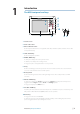
The NSS front panel and keys SIMRAD 4 5 STBY AUTO PUS H 1 Introduction TO EN TER MARK MENU GOTO PAGES IN MOB OUT MOB 6 7 8 9 10 NSS 7 1 2 2 3 1 Touch screen 2 Card reader door 3 Micro-SD Card reader Used for optional Navionics or InsightHD chart data, software updates, transfer of user data and system backup. 4 STBY / AUTO key Used for autopilot operation. 5 MARK / MENU key A short press displays the active panel’s menu. A double press displays the Settings menu.
The NSS screen 1 4 See “Customizing your system” on page 82 for further information 2 5 6 3 7 8 1 Instrument bar Navigation and sensor info can be viewed in a user configurable instrument bar on top of your pages. 2 Panel button You can tap the text on this area to end an ongoing operation, e.g. to remove the cursor from the screen, to end route editing and to stop measuring distance. 3 Dialogs Dialogs are used for user input or for presenting information to the user.
The system includes the following page groups, which each have a pre-configured combination of panels: Icon See “Customizing your system” on page 82 for further information Description Main page Instruments with configurable live data from system internal, and external sources such as engines Instruments Echosounder Echosounder Live video Video Navigation information Steering Insight or Navionics charts, depending on region Chart Radar Radar The main page in each group is a full size panel.
8 The Control pages The Control pages give access to page selection, tools and settings. The Pages overview panel (Home) is displayed by pressing the PAGES key. Repeated presses on this key will toggle between the control panels. You can also switch between the control panels by dragging your finger horizontally on the screen. All control panels and sub-panels are always full screen, and they will open on top of your previous page.
Basic operation 2 The power key Advanced power control The NSS can be wired and configured to control the power of displays and compatible devices. See the NSS Installation manual for more information. • Press and hold: Turn unit on/off • Single press: Display dialog for light adjustment, standby mode and radar standby/ transmit • Repeated presses: Toggle preset brightness levels (10 - 6 - 3- 1) Note: If the power key is released before shut-down is completed, the power off is cancelled.
Select active panel In a split screen you have multiple panels, but only one panel can be active at a time. You will only be able to access the context menu of the active panel. The active panel is outlined with a red border. You can switch between active panels by tapping the required panel. The menus Menus are used to operate the system and to adjust settings.
Placing the cursor The cursor is by default not shown on any panel. You tap the screen to place the cursor on a Chart, Radar or Echosounder panel. The cursor information window will show position coordinates at the cursor position, and range and bearing to the vessel. On an Echosounder panel, the cursor information window will include the depth at cursor position. Further use of the cursor is described in the Chart, Radar and Echosounder sections.
Charts 3 The chart function displays your vessel’s position relative to land and other chart objects. On the panel you can plan and navigate routes, place waypoints, overlay a radar image or weather information, and display AIS targets. The NSS has different embedded cartography depending on region. Units sold in America will include Insight cartography, while units sold in other regions will have embedded Navionics coastal (Silver) cartography split by region.
Using the cursor on the chart panel The cursor is by default not shown on the chart panel. When you tap the screen, the cursor will become visible and the cursor position window will be activated. When the cursor is active, the chart will not pan or rotate to follow the vessel. To remove the cursor and cursor window from the panel, press the X key or tap the Clear cursor panel key. Pressing the X key repeatedly will toggle the chart center between the vessel and the cursor position.
Positioning the chart on the panel Chart orientation Several options are available for how the chart is rotated in the panel. The chart orientation symbol in the panel’s upper right corner indicates the north direction. North up Heading up Course up North up Displays the chart with the north direction upward. Corresponds to the usual orientation of nautical charts. Heading up Displays the chart with the vessel’s heading directly up on the chart image. Heading information is received from a compass.
3D chart view options There are two 3D views available: • Vessel mode - default mode keeping the boat in center on the chart panel • Explore mode - allows you to move the 3D chart view away from the vessel You toggle between these two modes by pressing the X key. Vessel mode In this mode the camera follows the vessel. The vessel’s position will be in center if not Look ahead option is selected. The camera angle is by default as seen from your eye position, looking toward the vessel.
Categories Insight charts includes several categories and sub-categories that you can turn on/off individually depending on which information you want to see on your display. Chart imagery style The charts can be displayed in two different imagery styles, either as 2D basic mapping style, or with shaded relief presenting chart including terrain imaging. 2D Shaded relief Navionics chart options Chart orientation and Look ahead See page 16.
Photo transparency The Photo transparency sets the opaqueness of the photo overlay. With minimum transparency settings the chart details will be almost hidden by the photo. Minimum transparency Transparency value = 10 Navionics Fish’n Chip NSS supports Navionics Fish’n Chip (US only) chart feature. For more information, see www.navionics.com. Optional settings for Navionics charts Colored Seabed Areas Used for displaying different depth areas in different shades of blue.
Range Rings Turns on/off range rings on the chart. The range rings can be used to present the distance from your vessel to other chart objects. The range scale is set automatically by the system to suit the chart scale. The vessels’ extension lines Sets the length of the extension lines for your vessel and for other vessels shown as AIS targets. COG The length of the extension lines are either set as a fixed distance, or to indicate the distance the vessel will move in the Heading selected time period.
4 Waypoints, routes & tracks Waypoints A waypoint is a user generated mark positioned on a chart, on a radar image or on an echosounder image. Each waypoint has an exact position with latitude and longitude coordinates. A waypoint positioned on an echosounder image, will in addition to position information have a depth value. A waypoint is used to mark a position you later may want to return to. Two or more waypoints can also be combined to create a route.
Moving a waypoint by tapping the screen 1. Select the waypoint by tapping it 2. Activate the menu and select the move option - The waypoint icon will change to indicate moving mode 3. Tap on the chart panel to select a new position 4. Confirm the new position by pressing the rotary knob, tapping the panel key or by using the options in the menu Routes A route consists of a series of routepoints entered in the order that you want to navigate them.
Creating a new track You define the track settings and start the new track from the Tracks Settings dialog described below. Track settings The track is made up of a series of track points connected by line segments whose length depends on the frequency of track recording. You can select to position track points based on time settings, distance, or by letting the NSS system position a waypoint automatically when a course change is registered.
5 Navigating with the NSS The navigation function included in the NSS allows you to navigate towards the cursor position, a waypoint or along a predefined route. For information about positioning waypoints and creating routes, refer “Waypoints, routes & tracks” on page 22. The Goto menu You can start navigation from any panel by using the Goto menu, displayed by pressing and holding the GO TO / MENU key.
Cancel navigation You cancel navigation from the Goto menu or the chart panel menu. Navigating with autopilot If an AC12, AC42 or an SG05 autopilot computer is connected to the system, autopilot functionality will be included in the NSS. When you start navigation on a system with autopilot functionality, you will be prompted to set the pilot to navigation mode. If you choose not to engage the autopilot, the pilot can later on still be set to navigation mode from the pilot menu.
Magnetic variation Magnetic variation is the difference between true bearings and magnetic bearings, caused by different location of the Geographic and the Magnetic north poles. Any local anomalies such as iron deposits might also affect the magnetic bearings. Magnetic variation is applied in order to navigate with heading in “True” mode. When set to Auto, the system automatically converts magnetic north to true north. Select manual mode if you need to enter your own local magnetic variation.
Data fields The Steer panel offers the following information: DTD Distance to destination BTW Bearing to waypoint SOG Speed over ground COG Course over ground TTD Time to destination ETA Estimated time of arrival at next waypoint VMG Velocity Made Good towards next waypoint. STEER Course to steer towards next waypoint The course line When travelling on a route the course line shows the intended course from one waypoint towards the next.
6 Using the autopilot If an AC12, AC42 or SG05 autopilot computer is connected to the system, autopilot functionality will be available in the NSS. An Autopilot is designed to maintain an accurate course in various sea conditions with minimal helm movements. Safe operation with the autopilot Warning: An autopilot is a useful navigational aid, but DOES NOT under any circumstances replace a human navigator.
The autopilot panel The autopilot panel is used to display information when you are navigating. It replaces the autopilot pop-up when used in full screen, or on any pages where it is used as a split pane. The autopilot mode indication bar will also not be shown when the autopilot panel is used. The shortcut icon used to activate the autopilot panel is by default available on the Pages panel. The panel can however only be used when an AC12, AC42 or SG05 computer is available on the network.
30 | Using the autopilot | NSS Operator Manual MODE Tacking Dodging Turn (Tacking) Mirrors the set wind angle to the opposite side of the bow Steers the boat to a specific waypoint location, or through a route of waypoints x Steers the boat to maintain the set wind angle x x Steers the boat to a specific waypoint location, or through a route of waypoints x x Resumes NoDrift mode after a heading change Keeps the boat on a straight bearing line Changes commanded heading with a pre-defined value x
Controlling steering performance in automatic modes The autopilot should be configured during installation and setup. Some parameters may be adjusted during operation to increase the steering performance. Refer to “The autopilot settings panel” on page 39. Using the autopilot in standby mode The autopilot must be in STBY mode when you steer the boat manually. You can switch the autopilot to STBY mode from any operation by a short press on the STBY/AUTO key.
Initiating a turn The illustration below shows how you start the spiral turn steering from the Autopilot menu. You select the turn direction and start the turn by tapping the left or right keys or by using the rotary knob. Stopping the turn You can at any time during a turn press the AUTO/STBD key to return to standby mode and manual steering. Turn variables All turn steering options, except the C-turn, have settings that you may adjust before you start a turn and at any time when the boat is in a turn.
Zigzag-turns For navigating in a zigzag pattern, you set the initial course change before the turn is started. During the turn you can alter the course change and the leg distance. The main course can be changed by turning the rotary knob.
Depth Contour Tracking, DCT TM If the system has input from an echosounder, the autopilot can be set to follow a depth contour. Warning: Do not use this feature unless the seabed is suitable. Do not use it in rocky waters where the depth is varying significantly over a small area. Slope Narrow channel Ridge Use the following process to initiate DCT steering; 1. 2. 3. 4.
NoDrift mode This mode combines the autopilot and the positioning information from the GPS. When NoDrift is activated, the autopilot will draw an invisible bearing line based on current heading from the boat’s position. Unlike in AUTO (compass) mode the autopilot will now use the position information to calculate the cross track error, and automatically keep your track straight.
The waypoint arrival circle The Arrival radius defines the point at which a turn is initiated when you are navigating a route. WP1 WP2 Arrival circles The arrival circle should be adjusted according to boat speed. The higher the speed, the wider the circle. The intention is to make the autopilot start the heading change in due time to make a smooth turn onto the next leg. The figure below may be used to select the appropriate waypoint circle when creating the route.
The set course to steer (CTS) and set wind angle are entered from the compass heading and the wind transducer at the moment the WIND mode is selected. From that point the autopilot will change the course to maintain the wind angle as the wind direction may change. Tacking Note: The tack function is only available when the system is set up for SAIL boat type. Tacking should only be performed into the wind and must be tried out in calm sea conditions with light wind to find out how it works on your boat.
When running, it is difficult to steer the boat with waves coming sideways or from behind. The waves may yaw the boat into an unwanted gybe; this can be hazardous for both the crew and the mast. The gybe prevent function will be activated when the actual apparent wind angle becomes greater than 175° or gets opposite to the set wind angle. More rudder will be commanded to prevent an unwanted gybe. The tack and gybe prevent functions are not a guarantee against getting into a hazardous situation.
The autopilot settings panel The Autopilot settings panel gives access to settings that might be changed by the user during operation of the autopilot. For information about installation, see the separate NSS Installation manual. Auto-hide Autopilot information is by default shown on top of the pages when the Autopilot pop-up is not displayed. You can select to turn this information off.
Sailing parameters Note: Sailing parameter settings are only available if the boat type is set to Sail. Tack time When performing a tack in WIND mode, the rate of turn (tack time) can be adjusted. This will give single-handed sailors time to handle the boat and the sails during a tack. A turn performed without shifting wind side, will also be made at a controlled turn rate.
Automatic steering This option displays an overview of all autopilot steering parameters, and you can adjust parameters if required. For more details, refer to the separate AC12/AC42 Installation manual. Installation Used for autopilot installation and commissioning. See the separate AC12/AC42 or SC05 Installation manual.
7 Using the radar The radar panel can be set up as a full screen view or combined with other panels. The radar image can also be displayed as an overlay to existing 2D chart views and 3D for Navionics. Refer to “Charts” on page 14. Note: Radar overlay requires data from heading sensor. The radar panel ge Range Headingg line * Rotary controls North Indicator * Orientationn Motion Compass * Range angge rings ri * Range markers mark ma rke * Data bar** * Optional radar symbology.
Optimizing the radar image You may be able to improve the radar image by adjusting the radar sensitivity, and by filtering out the random echoes from sea and weather conditions. You select between the control images by tapping the image or by pressing the rotary knob. Active control will expand and display its name in full. You can then adjust the value by turning the knob or by a vertical dragging movement on the control you want to adjust. Gain The gain controls the sensitivity of the radar receiver.
Offset Allows you to move the PPI center to any location on the radar panel. 1. Select the offset option from the menu 2. Tap the screen where you want to position the radar center 3. Confirm the setting by tapping the SAVE OFFSET key on top of the screen or by pressing the MENU key Center Look ahead Custom offset True motion In True motion your vessel, and moving targets, move across the Radar screen as you travel. All stationary objects remain in a fixed position.
Defining an EBL/VRM marker 1. 2. 3. 4. 5. Ensure that the cursor is not active on the radar panel (press the X key) Activate the menu Select one of the EBL/VRM markers Select adjustment method, and tap the screen to adjust the marker Tap the panel key to save the marker position When positioned, you can quickly turn the EBL/VRM on/off by tapping the relevant section on the data bar (NSS8 and NSS12 only). Quick EBL/VRM marker positioning by using the cursor 1. Tap the radar panel to position the cursor 2.
Target expansion Target expansion will override and increase the default radar pulse length, providing larger target returns. Target trails You can define how long time the trail that each target leaves should remain on your radar panel. You can also turn OFF target trails.
MARPA targets If the NSS includes a heading sensor, the MARPA function (Mini Automatic Radar Plotting Aid) can be used to track up to tem radar targets. You can define alarms to notify you if a target gets too close. Refer “MARPA target settings” on page 47. MARPA tracking is an important tool for collision avoidance. Note: MARPA requires heading data for both the radar and the NSS . MARPA target symbols The NSS system use the target symbols shown below. Symbol Description Acquiring MARPA target.
Target trails and safe rings You can define the length of the MARPA trail making it easier to follow target movement. A circle can be added around the MARPA target to present the danger zone. Refer “Defining dangerous vessels” on page 48. The vessels extension lines Sets the length of the extension lines for your vessel and for other vessels. The length of the extension lines is either set as a fixed distance, or to indicate the distance the vessel will move in the selected time period.
Radar settings panel Radar symbology You can turn on/off optional radar symbology individually from the Radar settings page. See illustration showing optional radar items on page page 42. Data bar Turns on/off the radar data bar. Refer illustration on page 42. The data bar can show up to 3 targets, arranged with the closest target on top. You can select to show MARPA targets on top and before any AIS targets, even if the AIS targets are closer to your vessel.
8 The echosounder The echosounder function provides a view of the water and bottom beneath your vessel, allowing you to detect fish and examine the structure of the sea floor. The echosounder displays the water column moving from right to left on the panel. You can select between single panel view and several split views as described later in this chapter.
Split screen options Zoom The Zoom mode presents a magnified view of the sounder image on the left side of the panel. By default the zoom level is set to 2x. You can select up to 8x zoom from the drop-down menu. The range zoom bars on the right side of the display shows the range that is magnified. If you increase the zooming factor the range will be reduced. You will see this as reduced distance between the zoom bars.
Adjusting color and gain settings Gain The gain controls the sensitivity of the echosounder. The more you increase the gain, the more details will be shown on the image. However, a higher gain setting may introduce more background clutter on the image. Conversely, if the gain is set too low weak echoes may not be displayed. Auto gain The Auto gain option will keep the sensitivity at a level that works well under most conditions.
Placing a mark on an echosounder image You can position a mark at the vessel’s position by pressing and holding the MENU key. You can position a mark on a selected echosounder item by tapping the screen and then activating the menu. Note: Only marks positioned by using the cursor will include depth information. Measuring distance The cursor can be used to measure the distance between the position of two observations on the sounder image.
When the echosounder image is being recorded, there will be a flashing red symbol and a message will appear periodically at the bottom of the screen. Recording symbol The graphics shows that both conventional echosounder and StructureScan data are being logged Logging message The sounder recording is stopped by re-selecting the Record function. Viewing the recorded sounder data Both internally and externally stored sounder records may be reviewed when selected.
The fish echoes You can select how you want the echoes to appear on the echosounder image. Traditional fish echoes Fish symbols and depth indication StructureScan™ overlay When a StructureScan unit is connected to your NSS system, you can overlay a DownScan image on the regular echo image. When activated as described below, the echosounder menu will expand to include basic StructureScan options. Gain for both images can be adjusted as described on “Adjusting color and gain settings” on page 52.
Overlay downscan When a StructureScan unit is connected to your NSS system, you can overlay DownScan images on the regular echo image. When activated, the echosounder menu will expand to include basic StructureScan options. See “StructureScan™ overlay” described previously. Recording and viewing the echosounder data See page 53. Search depth Noise may cause the echosounder to search for unrealistic depths.
9 StructureScan™ StructureScan™ is an optional hardware module that uses high frequency to provide a High resolution image of the seabed StructureScan™ provides a 150 m (480 ft) wide coverage in high detail with SideScan, while the DownScan™ provides picture perfect images of structure and fish directly below your boat, down to 90 m (300 ft). The StructureScan™ panel is accessed from the shortcut icon on the Pages panel when the StructureScan external box and transducer are fitted.
SideScan Range scale Left water column Right water column Surface Su urfface The range The range setting determines the water depth that is visible on the screen. Auto range When the range is set to Auto the system will automatically set the range depending on the water depth. Preset range levels You can select between several preset range levels. When manually changing the range the upper depth line will always be at the water surface.
DownScan image When zooming in on a DownScan image, the sea floor will be kept near to bottom of the screen, irrespective of whether it is in auto-range or manual range. If the range is set considerably less than the actual depth, the unit will not be able to find the bottom when zooming. If the cursor is active, the unit will zoom in where the cursor is pointed.
Measuring distance The cursor can be used to measure the distance between two observations on the StructureScan image. It is easier to use the measure function when the sounder image is paused. 1. Activate the menu to start the measure function - The cursor will be positioned in the middle of the panel, and the distance will be measured from this position 2.
The Instruments panels 10 The instrument panels consists of multiple gauges - analog, digital and bar - that can be customized to display selected data. The instrument panel displays data on dashboards, and you can define up to ten dashboards within the instrument panel. Note! To include fuel/engine information, engine and tank information has to be setup from the Settings panel.
11 Using AIS If an AIS device is connected, any targets detected by this devices can be displayed and tracked. You can also see messages and position for DSC transmitting devices within range. AIS targets can be displayed as overlay on radar and chart images, and this feature is an important tool for safe travelling and collision avoidance. You can define alarms to notify you if an AIS target gets too close or if the target is lost.
Viewing information about all AIS targets Chart pages You can view information about all AIS targets within range of your vessel from the menu. Radar pages The data bar includes information about up to 3 AIS targets. The targets are listed with the closest target on top, and are color coded to indicate target status. Note: Data bar is not available on NSS7.
Filtering the targets All targets are by default shown on the display if an AIS device is connect to the NSS system. You can select to not show any targets, or to filter the icons based on security settings, distance and vessel speed. The vessels extension lines The length of the extension lines for your vessel and for other vessels can be set by the user. The length of the extension lines is either set as a fixed distance, COG or to indicate the distance the vessel will move in the selected time period.
12 Audio When the NSS is connected to a SonicHub server you can use your unit to control audio playback from iPod, iPhone, USB mass storage device (mp3) and AM/FM radio. Before playing FM radio through the SonicHub, you must purchase a marine-grade AM/FM antenna. When connected to a WM-2 Satellite module you can subscribe and include Sirius™ audio on your NSS system.
Setting up the SonicHub speakers Speaker zones Your unit has four on-board amplified channels for directly driving speakers. There are also two low level channels (stereo) for supplying signal to an external amplifier, plus two mono channels for amplified subwoofer(s). The audio outputs are organized in 3 zones. You can adjust balance, volume and volume limit settings independently for each zone. Adjustments to the bass and treble settings will alter all zones. Refer graphics.
Audio playback Playback panel buttons • Tap Display source’s native menu • Tap Play previous track • Tap Play • Tap Play next track • Tap Display audio menu Shuffle and repeat Shuffle and repeat is turned on/off from the audio menu, or by tapping the icons in the media bar. The icons will be red when the function is turned on. The playback menu The playback menus includes an option giving access to the source’s native menu or file structure, used for selecting tracks.
Using Sirius radio The Sirius panel buttons • Tap and hold Tune in to a Sirius radio channel • Tap Goto previous/next station in favorite list • Tap Display audio menu The channels list The channels list displays all available Sirius channels, whether or not you have a subscription for the channel. The favorite list You can create of list of your favorite Sirius channels from within the channels list. You will not be able to add unsubscribed channels.
13 SiriusXM™ weather (North America only) When connected to a Navico Weather Module WM-2, you can subscribe and include Sirius™ audio and Sirius™ Marine Weather Service on your NSS system (North America only). Sirius™ audio and weather service covers inland US waters and coastal areas into the Atlantic and Pacific oceans, Gulf of Mexico and the Caribbean Sea. The audio and weather products received vary depending on your selected subscription package. For more information refer to www.siriusxm.
Weather symbology Precipitation Shades of color are used to show precipitation type and intensity. Darkest color indicates highest intensity. Precipitation type Color codes Rain From light green (light rain) - yellow - orange - to dark red (heavy rain) Snow Blue Mixed Pink Sea surface temperature (SST) Can be shown as color shading or text. When color coding is selected, the SST color bar will be shown on the left side of the display.
Weather overlay transparency The opaqueness of the weather overlay can be adjusted. Min transparency Max transparency Weather alarms You can setup the lightning or storm alarms to be within a certain range of your vessel. You can also get an alarm is a severe weather forecast alarm is issued for your chosen marine zone. A watchbox is defined by the National Weather Service. When the alarm is turned on you will get an alarm if your vessel is inside or moves into a watchbox.
14 Using Video The video function allows you to view videos or camera sources on your NSS screen. For information about how to connect the camera, see the separate NSS Installation manuals Note: The video images will not be shared via the network. You can only view the video on the unit connected to the video source. The video panel The video image will be proportionally scaled to fit into the video panel. Area not covered by the image will be colored black.
Mirroring the video image Video input can be set to display a mirrored image. This setting can be helpful for rear-facing cameras used to back-down the vessel. The video standard NSS supports NTSC and PAL video. The two channels are set up individually. Check the local video standard or the standard of your cameras.
15 BEP CZone The NSS system integrate with BEP’s CZone system used for controlling and monitoring a distributed power system on your vessel. A separate manual will be provided with your CZone system. Refer to this documentation and to the NSS Installation for how to install and configure the CZone system. The BEP CZone panel When the CZone system is connected and configured, the CZone icon will be available on the Tools panel.
Enables you to monitor all on board parameters including tank levels displayed in graphical, percentage and volume remaining formats. Shows control options and monitoring information. Displays visual and audible alarms that can be set for high and low levels. The CZone info panel When the CZone is installed and configured, an additional CZone dashboard will be added to the Instrument panels.
16 The alarm system The NSS system will continuously check for dangerous situations and system faults while the system is running. When an alarm situation occurs, an alarm message will pop up on the screen. If you have enabled the siren, the alarm message will be followed by an audible alarm, and the switch for external alarm will go active. The alarm is recorded in the alarm listing so that you can see the details and take the appropriate corrective action.
The alarms dialog The alarms can be setup in the Alarms dialog. This dialog also includes information about active alarms and alarm history. The alarms are described in the chapter describing the corresponding feature. E.g. all autopilot alarms are described in the Autopilot section.
17 The Tools page The Tools dialog includes options and tools that are not specific to any panel. This dialog and sub-screen dialogs are always full screen. A tools dialog will open on top of your previous page. When you close one of these dialogs the display will return to last active page. Any listing in the tools dialogs has a page menu, giving access to available options for the selected item. The menu is displayed by tapping and holding on the screen or by pressing the MENU key.
Find Search function for several chart items. Waypoints/routes/tracks List of waypoints, routes and tracks with details. Tap on the waypoint, route or track you wish to edit or delete Trip Log Trip 1 / Trip 2 Displays voyage and engine information, with reset option for all data fields. Today Displays voyage and engine information for current date. All data fields will be automatically reset when the date changes.
Files File management system for files, waypoints, routes, tracks and settings. CZone CZone will appear when the system is connected to a CZone system. This allows for access to control, monitoring and alarms associated with Czone circuits. It also allows selection of custom operational modes if these have been configured.
Customizing your system 18 Page overview The Pages group overview The Pages group overview is pre-configured with 6 page groups and with 3 shortcut icons to Autopilot panel, to a combined Chart/Echosounder panel, and to the StructureScan™ panel. The pre-configured shortcuts can be removed or modified by the user. The page group panels Each of the 6 page group panels are pre-configured with a combination of pages: The main page in each group is a full size panel.
Deleting a page All pre-configured and user defined pages, except the main page for the page group, can be deleted. 1. Tap and hold on the page icon for the page you want to remove. You can also select the icon with the rotary knob and then pressing the MENU key 2. Select the delete option from the menu Setting the appearance of the instrument bar Data sources connected to the system can be viewed in the instrument bar on top of your pages.
Language Controls the language used on this unit for panels, menus and dialogs. Changing the language will make the unit re-start. Text size Used for setting the text size on menus and dialogs. Default setting: Normal Key beeps Controls the loudness of the beep sound when a key is pressed. Default settings: On Time Controls the local time zone offset, and the format of the time and date. Audio Used for activating the audio media bar at the bottom of the pages.
19 Using the simulator Simulator mode The simulation feature will let you see how the unit works in a stationary position and without being connected to echosounder, radar, GPS etc. You can use the simulator to help you become familiar with your unit before using it out on the water. When the simulator is toggled on this is indicated in the lower part of the display.
20 Maintenance Preventive maintenance The NSS unit does not contain any field serviceable components, therefore the operator is required to perform only a very limited amount of preventative maintenance. It is recommended that you always fit the supplied protective sun cover when the unit is not in use. Simple maintenance procedures Cleaning the display unit The supplied cleaning cloth should be used to clean the screen, where possible. Use plenty of water to resolve and take away salt remains.
Backing up your system data Waypoints, routes, tracks that you create are filed on your system. It is recommended to regularly copy these files and your system settings files as part of your back-up routine. The files are copied to a Micro-SD card inserted in the card slot on the front of your unit.
21 Menu and dialog overview Panel menus The graphics below shows panel specific menus without and with active cursor on the panel. A panel menu is displayed by pressing the MENU key, by tapping the MENU pannel button or by tapping and holding on the panel. Chart Instruments Note: Chart menu will be extended if overlay is selected. Echo Video Structure Autopilot Radar Goto menu This menu is displayed on any panel by pressing and holding the GO TO / PAGES key.
Settings dialogs The Settings overview page is available by repeated presses on the PAGES key.
Navigation settings Units settings Fuel settings Network settings Tracks settings Vessels settings Alarms settings Simulator settings Menu and dialog overview | User Guide Style Template | 89
22 90 | Index A About this manual 1 AIS 62 Defining dangerous vessels 64 Filtering the targets 64 Icon orientation 64 Selecting targets 62 Target symbols 62 Vessel alarms 63 Vessel settings 63 Alarms 76 Acknowledging a message 76 Dialog 77 History 77 Limits 25 Listing 78 Message 9 Messages 76 Multiple alarms 76 Single alarms 76 Vessel 63 Waypoint 21 Weather 71 Audio 65 FM/AM radio 67 Media bar 65 Menus 65 Operating the audio source 66 Rotary knob 66 Sirius radio 68 SonicHub speakers 66 Autopilot 28 Activa
Customizing your system 81 D Data fields 27 Datum 26 Declarations 1 Demo mode 84 Dialog boxes 12 Scroll by dragging the list 12 Dialog overview 87 Dialogs 8 E Echosounder 50 Clarity 55 Color settings 52 Cursor 52 Frequency 51 Gain settings 52 Image items 54 Measuring distance 53 Network 55 Noise rejection 51 Options 54 Overlay downscan 56 Palettes 54 Panel 50 Pause 53 Ping speed 55 Placing a mark 53 Recording 53, 56 Rotary knob 52 Scroll speed 51 Search depth 56 Settings 55 Split screen options 51 Structu
Deleting a page 82 Eshosounder panel 50 Instruments panels 61 MENU panel button 9 Pages group overview 81 Panel button 8 Panel menus 87 Position panels 27 Radar panel 42 Select 11 Steer panel 26 Tools page 78 Video panel 72 Panel menus 87 Position panels 27 Power control 83 Power key 11 R Radar 42 Alarm settings 45 Center 43 Cursor 42 Data bar 49 Defining dangerous vessels 48 EBL/VRM 44 Fast scan 46 Gain 43 Guard zone 45 Image 43 Installation 49 Interference 43 Look Ahead 43 MARPA settings 49 MARPA targets
T Target symbols 62 Technical information 83 Text size 83 Tides 79 Time and date 83 Tools page 78 Touch screen, basic operation 11 Tracks 22 Creating new 23 Listing 79 Panel 23 Settings 23 Trip Log 79 Trouble shooting 85 V Vessel status listing 78 Vessel symbol 14 Video 72 Adjusting image 72 Menus 72 Panel 72 Source 72 W Warranty 1 Waypoints 21 Alarm settings 21 Dragging waypoints 15 Edit 21 Listing 79 Panel 23 Placing waypoints 15 Positioning 21 Index | NSS Operator Manual | 93
*988-10102-002* www.bandg.com www.simrad-yachting.com www.lowrance.