NSS evo2 Operator Manual ENGLISH simrad-yachting.
Preface Disclaimer As Navico is continuously improving this product, we retain the right to make changes to the product at any time which may not be reflected in this version of the manual. Please contact your nearest distributor if you require any further assistance. It is the owner’s sole responsibility to install and use the instrument and transducers in a manner that will not cause accidents, personal injury or property damage.
About this manual This manual is a reference guide for operating the Simrad NSS evo2 systems. It assumes that all equipment is installed and configured, and that the system is ready to use. The manual assumes that the user has basic knowledge of navigation, nautical terminology and practices. Important text that requires special attention from the reader is emphasized as follows: Ú Note: Used to draw the reader’s attention to a comment or some important information.
Contents 9 Introduction 9 10 11 12 13 13 The front panel and keys The Home page Application pages Integration of 3rd party devices GoFreeTM wireless OP40 Remote controller 14 Basic operation 14 14 14 15 16 16 17 17 17 18 18 19 19 Turning the unit on and off Display illumination Locking the touch screen Touch screen operation Using menus and dialogs Selecting pages and panels Adjusting panel size Adding new favorite pages Edit favorite pages Customizing the Home page background Setting the appearance of
37 Autopilot 37 37 37 37 38 39 40 40 40 40 41 41 42 43 44 45 46 46 Safe operation with the autopilot Activating the autopilot Switching from automatic mode to manual steering Autopilot indication on the pages The Autopilot panel Mode overview Standby mode Non-Follow Up (NFU, Power steering) Follow-up steering (FU) AUTO mode (auto compass) NoDrift mode NAV mode WIND mode WIND Nav mode Turn pattern steering Using the NSS evo2 in an AP24/AP28 system Using the autopilot in an EVC system Autopilot settings 49
69 StructureMap 69 69 69 70 70 70 71 The StructureMap image Activating Structure overlay StructureMap sources StructureMap tips Recording StructureScan data Using StructureMap with mapping cards Structure options 72 AIS 72 73 74 75 75 AIS target symbols Viewing information about AIS targets AIS SART Vessel alarms Vessel settings 78 Instrument panels 78 78 Dashboards Customizing the Instrument panel 79 Audio 79 80 81 82 82 82 Enabling audio The Audio panel Setting up the audio system Operating the aud
94 94 Files Find 95 Simulator 95 95 95 96 About the simulator Demo mode Selecting simulator source files Advanced simulator settings 97 Maintenance 97 97 97 97 97 97 98 98 8 Preventive maintenance Cleaning the display unit Cleaning the media port door Checking the keys Checking the connectors NMEA 0183 Data logging Software upgrades Backing up your system data Contents | NSS evo2 Operator Manual
1 Introduction The front panel and keys Key Description 1 Touch screen 2 Power key Press once to display the System control dialog. Repeat short presses to cycle the backlight brightness. Press and hold to turn the unit ON/OFF. 3 Rotary knob Rotate to scroll through menu items, then press to confirm a selection. Rotate to adjust a value. Rotate to zoom a zoomable panel. 4 STBY / AUTO key With the autopilot in any automatic mode: Press to set the autopilot to Standby mode.
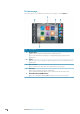
The Home page The Home page is accessed from any operation by a short press on the Home key. Key 10 Description 1 Applications Tap a button to display the application as a full page panel. Press and hold a button to display pre-configured split page options for the application. 2 Tools Tap a button to access dialogs used for carrying out a task, or for browsing stored information. 3 Close button Tap to exit the Home page and return to the previous active page.
Application pages Each application connected to the system is presented on panels. The application can be presented as a full page, or incombination with other panels in a multiple panel page. All pages are accessed from the Home page. Key Description 1 Application panel 2 Instrument bar Navigation and sensor information. The bar can be tuned off and it can be configured by the user. 3 System Control dialog Quick access to basic system settings.
Pre-configured split pages (optional). here concept your of description short a Enter Each full screen applications have several pre-configured split pages, featuring the selected application combined with each of the other panels. Ú Note: The number of split pages can not be changed, and the pages can not be customized or deleted. You access a split page by pressing and holding the main panel button. Favourite pages (optional).
BEP CZone integration The NSS evo2 system integrate with BEP’s CZone system used for controlling and monitoring a distributed power system on your vessel. The CZone icon will be available in the Tools panel on the Home page when a CZone system is available on the network. A separate manual is provided with your CZone system. Refer to this documentation and to the NSS evo2 Installation manual for how to install and configure the CZone system.
Turning the unit on and off (optional). here concept your of description short a You turn the unit on and off by pressing and holding the Power key. If the key is released before the shut-down is completed, the power off process is cancelled. You can also turn the unit off from the System controls dialog, activated by a short press on the Power key. Enter 2 Basic operation Ú Note: The System Controls dialog will not display the power off option when the unit is configured as slave.
Touch screen operation Basic touch screen operation on the different panels is shown in the table below. The panel sections later in this manual have more information about panel specific touch screen operation.
Using menus and dialogs Menus You display a page menu by tapping the MENU button in the upper right corner of the page. • Select a menu item and toggle on/off a checkbox by tapping it • Adjust a slide bar value by either: • dragging the slide bar • tapping the + or - icons You can also operate the menus by using the rotary knob.
Adjusting panel size (optional). here task your of description short a Enter You can change the panel size for an active split page. The panel size can be adjusted for both favorite pages and for predefined split pages. 1. Activate the System control dialog by pressing the Power key or by dragging your finger from the top of the screen 2. Select the adjust splits option in the dialog 3. Drag the adjustment icon to resize the panel 4.
Customizing the Home page background (optional). here concept your of description short a Enter The Home page's background can be customized. You can select one of the pictures included with the system, or you can used your own picture in .jpg or .png format. The images can be available on any location that can be seen in the files browser. When a picture is chosen as the wallpaper, it is automatically copied to the Wallpaper folder.
Positioning a Man Over Board mark If an emergency situation should occur, you can position a Man Over Board mark at the vessel’s current position by pressing the Home key followed by the MOB button on the Home page.
3 Charts The chart function displays your vessel’s position relative to land and other chart objects. On the chart panel you can plan and navigate routes, place waypoints and display AIS targets. You can overlay a radar image, a StructureScan image or weather information. The NSS evo2 is delivered with different cartography depending on region. All units will support Navionics Platinum Plus, TurboView and C-Map (by Jeppesen) via micro-SD card or via the Ethernet network.
Showing dual chart types (optional). here concept your of description short a Enter If you have different chart types available - embedded, in the card slot or on the Ethernet you can show two different chart types simulatanously on a page with two chart panels. You can select a dual chart panel by pressing and holding the Chart application button on the Home page, or by creating a Favorite page with two chart panels. Selecting chart type Chart type is set individually for each chart panel.
North up Displays the chart with the north direction upward. Corresponds to the usual orientation of nautical charts. Heading up Displays the chart with the vessel’s heading directly up on the chart image. Heading information is received from a compass. If heading is not available, then the COG from the GPS will be used. Course up Rotates the chart in the direction of the next waypoint when navigating a route or navigating to a waypoint.
The Cursor assist function (optional). here concept your of description short a Enter The cursor assist function allows for fine tuning and precision placement of the cursor without covering details with your finger. Press and hold your finger on the screen to switch the cursor symbol to a selection circle, appearing above your finger. Without removing the finger from the screen, drag the selection circle over the desired item to display item information.
Ú Note: You must have a SIRIUS data package subscription to search for fueling stations and an AIS receiver connected to search for vessels. 3D charts (optional). here concept your of description short a Enter The 3D option provides a three dimensional graphical view of land and sea contours. Ú Note: All chart types work in 3D mode, but without 3D cartography for the appropriate area the chart will appear flat.
(optional). here concept your of description short a Enter Insight view options (optional). here concept your of description short a Enter Insight Chart Details Low Basic level of information that cannot be removed, and includes information that is required in all geographic areas.
Rock filter level Hides rock identification on the chart beneath a given depth. This helps you to declutter charts in areas where there are many rocks located at depths well below your vessel draught. Navionics view options Chart shading Shading adds terrain information to the chart. Dynamic tide and current icons Shows tides and currents with a gauge and an arrow instead of the diamond icons used for static tides and current information.
Photo overlay Photo overlay enables you to view satellite photo images of an area as an overlay on the chart. The availability of such photos is limited to certain regions. You can view photo overlays in either 2D or 3D modes. No Photo overlay Photo overlay, land only Full Photo overlay Photo transparency The Photo transparency sets the opaqueness of the photo overlay. With minimum transparency settings the chart details will be almost hidden by the photo.
Chart settings Settings and display options made in the Chart settings page are common for all chart panels. 3D boat selection Determines which icon to use on 3D charts. Range Rings The range rings can be used to present the distance from your vessel to other chart objects. The range scale is set automatically by the system to suit the chart scale. Vessels’ extension lines Sets the length of the extension lines for your vessel and for other vessels shown as AIS targets.
Waypoints A waypoint is a user generated mark positioned on a chart, on a radar image or on an echosounder image. Each waypoint has an exact position with latitude and longitude coordinates. A waypoint positioned on an echosounder image, will in addition to position information have a depth value. A waypoint is used to mark a position you later may want to return to. Two or more waypoints can also be combined to create a route. Saving waypoints (optional).
Routes A route consists of a series of routepoints entered in the order that you want to navigate them. When you tap a route on the chart panel it will turn green, and the route name will be displayed. Creating a new route on the chart panel 1. 2. 3. 4. 5.
Edit a route from the chart panel 1. Tap the route to make it active 2. Select the route edit option in the menu 3. Tap the panel to add a new routepoint - If you tap on a leg a new point will be added between existing routepoints - If you tap outside the route the new routepoint will be added after the last point in the route 4. Drag a routepoint to move it to a new position 5. Save the route by selecting the save option in the menu. Ú Note: The menu will change depending on the selected edit option.
Track settings The track is made up of a series of track points connected by line segments whose length depends on the frequency of track recording. You can select to position track points based on time settings, distance, or by letting the NSS evo2 system position a waypoint automatically when a course change is registered. Ú Note: The Tracks option must also be turned ON in the chart settings to be visible. Waypoints, routes and tracks dialogs (optional).
5 Navigating The navigation function included in the NSS evo2 allows you to navigate towards the cursor position, towards a waypoint or along a predefined route. If autopilot functionality is included in your system, the autopilot can be set to automatically navigate the vessel. For information about positioning waypoints and creating routes, refer to "Waypoints-RoutesTracks" on page 29. Navigation panels The Nav and Position panels can be used to display information when you are navigating.
Data Fields (optional). here concept your of description short a Enter The Steer panel offers the following information: DTD Distance to destination BTW Bearing to waypoint SOG Speed over ground COG Course over ground TTD Time to destination ETA Estimated time of arrival at next waypoint VMG Velocity Made Good towards next waypoint. STEER Course to steer towards next waypoint Position panels You can switch between displaying the Nav panel or the Position panel.
Starting a route from the chart panel Tap a route on the panel, and then select the route navigation option from the menu. You can tap a routepoint to start navigating from a selected position. Start navigating a route from the Route dialog You can start navigating from the Route dialog, activated by: • Selecting the Route tool from the Home page • Selecting the route details from the menu Cancel navigation When you are navigating a route the menu will include an option for cancelling the route.
Navigation method (optional). here concept your of description short a Enter Different methods are available for calculating the distance and bearing between any two points on a chart. The Great circle route is the shortest path between two points. However, if you are to travel along such a route, it would be difficult to steer manually as the heading would constantly be changing (except in the case of due north, south, or along the equator). Rhumb lines are tracks of constant bearing.
If an AC12N, AC42N or SG05 autopilot computer is connected to the system, autopilot functionality will be available in the NSS evo2. An Autopilot is designed to maintain an accurate course in various sea conditions with minimal helm movements. Safe operation with the autopilot Warning: An autopilot is a useful navigational aid, but DOES NOT under any circumstances replace a human navigator.
Autopilot mode indication in the Status bar The Status bar will show autopilot information as long as an autopilot computer is connected to the network. Icons will be included if the autopilot is passive or locked by another autopilot control unit. Autopilot pop up You control the autopilot from the pop-up. The pop-up has a fixed position on the page, and it is available for all pages except when an Autopilot panel is active.
Data fields The following abbreviations are used in the autopilot panel: CTS Course to steer DTD Distance to destination SOG Speed over ground COG Course over ground DTW Distance to next waypoint XTE Cross track error (L: left or R: right) Mode overview The autopilot has several steering modes. Number of modes and features within the mode depend on boat type and available inputs, as shown in table. Mode Feature Description Standby Standby mode used when manually steering at the helm.
Standby mode Standby (STBD) mode is used when you steer the boat at the helm. • Switch the autopilot to STBY mode from any operation by a short press on the STBY/AUTO key. Non-Follow Up (NFU, Power steering) In NFU mode you use the port and starboard arrow buttons in the autopilot pop-up to control the rudder. The rudder will move as long as the button is pressed. • Select NFU mode by tapping the port or starboard arrow button in the pop-up when the autopilot is in STBY or FU mode.
You can interrupt the tack operation as long as the tack dialog is open by selecting the opposite tacking direction. When interrupted the boat will return to the previous set heading. NoDrift mode (optional). here task your of description short a Enter NoDrift mode combines the autopilot and the positioning information from the GPS. In NoDrift mode the vessel is steered along a calculated track line in a direction set by the user.
Waypoint arrival circle The Arrival radius defines the point at which a turn is initiated when you are navigating a route. The arrival circle should be adjusted according to boat speed. The higher the speed, the wider the circle. The intention is to make the autopilot start the heading change in due time to make a smooth turn onto the next leg. The figure below may be used to select the appropriate waypoint circle when creating the route.
Tacking in WIND mode Ú Note: The tack function is only available when the system is set up for SAIL boat type. Tacking should only be performed into the wind and must be tried out in calm sea conditions with light wind to find out how it works on your boat. Due to a wide range of boat characteristics (from cruising to racing boats) the performance of the tack function may vary from boat to boat.
Turn pattern steering The autopilot includes a number of automatic turn steering features for power boats when the pilot is in AUTO mode. Ú Note: The turn steering option will not be available if the boat type is set to sailboat - instead the tack/gybe feature is implemented. Initiating a turn You start the turn by tapping the relevant turn icon, followed by tapping the port or startboard options in the turn dialog to select the turn direction.
Lazy S-turn (optional). here concept your of description short a Enter In the lazy-s turn the boat will yaw around the main heading. You set the selected heading change before the turn is started. During the turn you can alter the main heading, the heading change and the turn radius from within the turn dialog. Depth contour tracking, DCTTM (optional).
Locking remote stations The AP24/AP28 includes a Remote Lock function that will disable autopilot control from other units. A locked NSS evo2 unit is indicated with a key symbol in autopilot controller popup. When the remote lock function is enabled on an AP24/AP28 control unit, only the active control unit stays in command. No transfer of command to NSS evo2 or other autopilot control units on the system can take place, You can only unlock the remote stations from the AP24/AP28 unit in command.
Sea state filter The Seastate filter is used to reduce rudder activity and autopilot sensitivity in rough weather. OFF Seastate filter is disabled. This is default AUTO Reduces rudder activity and autopilot sensitivity in rough weather by an adaptive process. The AUTO setting is recommended if you want to use the seastate filter MANUAL Linked to the steering response control settings described previously.
Response By default the system switches between HI/LO parameter set based on speed (motor boats) or speed and wind (sail boats). You can however select to manually set which parameter set that shall be used. HI or LO must be selected if no speed input is available. You can manually fine tune each of the two (HI/LO) parameter sets. Level 4 is default with parameter values as set by the autotune function. If no autotune is made (not recommended) the level 4 values are the factory default values.
7 Radar The radar panel can be set up as a full screen view or combined with other panels. The radar image can also be displayed as an overlay to existing 2D and 3D chart views. Refer to the section. Ú Note: Radar overlay requires data from heading sensor The radar panel Key Description Comment 1 Range 2 Orientation 3 Motion 4 Compass * 5 Heading line * 6 Rotary controls 7 Range rings * 8 Range markers * 9 Data bar * Optional radar symbology.
Radar operational modes The radar’s operational modes are controlled from the NSS evo2 unit. The following modes are available: Off The power to the radar scanner is turned off Standby The power to the radar scanner is on, but the radar is not transmitting. Transmit The scanner is on and transmitting. Detected targets will be drawn on the radar PPI (Plan Position Indicator). Radar Range (optional).
Adjusting the radar image You may be able to improve the radar image by adjusting the radar sensitivity, and by filtering out the random echoes from sea and weather conditions. The radar control images are located in the upper right corner of the radar panel. You select between the control images by tapping the image or by pressing the rotary knob. Active control will expand and display its name in full. You can then adjust the value by turning the rotary knob or by using the slide bar.
Advanced radar options Radar threshold The threshold sets required signal strength for the lowest radar signals. Radar returns below this limit will be filtered and not displayed. Default value: 30%. Target boost The target boost option is used for increasing the size of radar targets. Target expansion Target expansion will override and increase the default radar pulse length, providing larger target returns. Fast scan (Broadband Radar™ only).
North up Rotates the radar image with the north direction upwards. Course up Rotates the radar image to display the current navigation course directly up. This option works only when the NSS evo2 is navigating an active route. If you are not navigating an active route the heading up orientation will be used until the navigation function is started.
Defining an EBL/VRM marker 1. Ensure that the cursor is not active 2. Activate the menu, select EBL/VRM, then select EBL/VRM 1 or EBL/VRM 2 3. Select the adjustment option, and adjust the marker by dragging it into position on the radar panel 4. Select the save option in the menu to save your settings. Placing EBL/VRM markers by using the cursor 1. Tap the radar panel to position the cursor 2. Activate the menu 3.
MARPA targets If the NSS evo2 system includes a heading sensor, the MARPA function (Mini Automatic Radar Plotting Aid) can be used to track up to ten radar targets. You can define alarms to notify you if a target gets too close. Refer "Radar settings panel" on page 56. MARPA tracking is an important tool for collision avoidance. Ú Note: MARPA requires heading data for both the radar and the NSS evo2. MARPA target symbols The NSS evo2 system use the target symbols shown below.
MARPA alarm settings You can define the following MARPA alarms. Alarm ID Description MARPA target lost Controls whether an alarm shall be activated when a MARPA target is lost MARPA unavailable Controls whether an alarm shall be activated if you do not have the required inputs for MARPA to work (valid GPS position and heading sensor connected to the radar server) Recording radar data (optional).
Installation The Installation option is used for radar installation, described in the separate NSS evo2 Installation manual.
8 Echosounder The echosounder function provides a view of the water and bottom beneath your vessel, allowing you to detect fish and examine the structure of the sea floor. Except for the NSS evo2 M-versions, all units have built in CHIRP echosounder and StructureScan. The units may be connected to a variety of transducers. Ú Note: StructureScan and CHIRP can not be operated simultaneously on the NSS evo2.
Zooming an Echosounder image You zoom an Echosounder image by: • turning the rotary knob • using the panel zoom icons • by pinching or spreading on the screen Zoom level is shown on the upper left side of the panel. When zooming in, the sea floor will be kept near the bottom of the screen, irrespective of whether it is in auto-range or manual range. If the range is set considerably less than the actual depth, the unit will not be able to find the bottom when zooming.
Saving waypoints (optional). here concept your of description short a Enter You can save a waypoint at a selected position by tapping the panel, then selecting the new waypoint option in the menu. • If your unit has a MARK key, you can press this key to immediately save a waypoint. If the cursor is active the waypoint will be saved at cursor position. If the cursor is not active the waypoint will be saved at your vessel's position.
Auto gain The Auto gain option will keep the sensitivity at a level that works well under most conditions. With the gain in auto mode, you can set a positive or negative offset that gets applied to the auto gain. This is indicated as A-40 - A40. Color Strong and weak echo signals have different colors to indicate the different signal strengths. The colors used depend on which palette you select.
Log in XTF format Optional logging format for SideScan data. This will only be shown when StructureScan data is available. This format does not log all channesl into onen file. The format is used for third part application support on PC (like SonarWiz) that needs access to the StructureScan data. Create StructureMap when completed If StructureScan is available on the network, you can convert the loggings to StructureMap format (.smf) after recording.
A-Scope (optional). here concept your of description short a Enter The A-scope is a display of real-time echoes as they appear on the panel. The strength of the actual echo is indicated by both width and color intensity. Zoom bars (optional). here concept your of description short a Enter The zoom bars shows he range that is magnified on a split panel with zoom view. Fish ID (optional).
The log file is displayed as a paused image, and you control the scrolling and display from the menu. You can use the cursor on the image, measure distance and set view options as on a live echosounder image. If more than one channel was recorded in the selected echosounder file, you can select which channel to display. You exit the view function by tapping the X in the upper right corner. Search depth Noise may cause the echosounder to search for unrealistic depths.
9 StructureScan™ StructureScan HDTM uses hight frequencies to provide a high resolution, picture-like image of the seabed. StructureScan™ provides a 150 m (480 ft) wide coverage in high detail with SideScan, while the DownScan™ provides picture perfect images of structure and fish directly below your boat, down to 90 m (300 ft). StructureScan™ is integrated on NSS evo2Combo units. For NSS evo2Mapping units an optional hardware module must be connected to use the StructureScan features.
Using the cursor on the StructureScan™ panel The cursor is by default not shown on the StructureScan image. When you tap the screen the cursor will appear, and the information window and the history bar will be activated. On a SideScan image the left/right distance from the vessel to the cursor are shown at the cursor position. On a DownScan image the depth will be shown at cursor position. To remove the cursor and cursor elements from the panel, press X key or select the Clear cursor option.
(optional). here concept your of description short a Enter Setting up the StructureScan image Range The range setting determines the water depth that is visible on the screen. Auto range When the range is set to Auto the system will automatically set the range depending on the water depth. Preset range levels You can select between several preset range levels. Custom range This option allows you to manually set both upper and lower range limits.
Advanced StructureScan settings Noise rejection Signal interference from bilge pumps, engine vibration and air bubbles can clutter the image. The noise rejection option filters the signal interference and reduces the on-screen clutter. TVG (optional). here concept your of description short a Enter The TVG (Time Variable Gain) option compensate for distance to the object, making echoes from equal sized objects appear with the same size on the echosounder image.
10 StructureMap The StructureMap™ feature overlays SideScan images from a StructureScan source on the map. This makes it easier to visualize the underwater environment in relation to your position, and aids in interpreting SideScan images. The StructureMap image The example below shows a chart panel with Structure overlay, combined with a traditional SideScan panel.
Saved files When Saved files are selected, the StructureMap file is overlaid on the map based on position information in the file. If the chart scale is large, the StructureMap area will be indicated with a boundary box until the scale is large enough to show Structure details. Saved mode is used to review and examine StructureMap files, and to position the vessel on specific points of interest on a previous scanned area.
Structure options You adjust the StructureMap settings from the Structure options menu. The menu is available when Structure overlay is enabled. Not all options are available when saved StructureMap files are used as source. Unavailable options are greyed. Range Sets the search range Transparency Sets the opaqueness of the Structure overlay.
11 AIS If an NAIS400, an AI50 or a NMEA 2000 VHF that can do AIS (Automatic Identification System) is connected to the NSS evo2 system, any targets detected by this devices can be displayed and tracked. You can also see messages and position for DSC transmitting devices within range. AIS targets can be displayed as overlay on radar and chart images, making this feature an important tool for safe travelling and collision avoidance.
(optional). here concept your of description short a Enter Viewing information about AIS targets (optional). here concept your of description short a Enter Searching for AIS items You can search for AIS targets from any panel by using Find option in the Tools panel. From a chart panel you can search for AIS targets by using the Find option in the menu. If the cursor is active, the system will search for vessels around cursor position.
AIS SART When an AIS SART (Search And Rescue beacon) is activated, it starts transmitting its position and identification data. This data is received by your AIS device. If your AIS receiver is not compliant with AIS SART, it interprets the received AIS SART data as a signal from a standard AIS transmitter. An icon is positioned on the chart, but this icon is an AIS vessel icon.
Vessel alarms You can define several alarms to alert you if a target shows up within predefined range limits, or if a previously identified target is lost. Alarm ID Description Dangerous vessel Controls whether an alarm shall be activated when a vessel comes within the predefined CPA or TCPA. See “Defining dangerous vessels” on page 45. AIS vessel lost Sets the range for lost vessels.
Your vessel’s MMSI number You need to have your own MMSI (Maritime Mobile Service Identity) number entered in the NSS evo2 system to be able to receive addressed messages from AIS and DSC vessels. It is also important to have the MMSI number entered to avoid seeing your own vessel as an AIS target on the chart. Ú Note: The Vessel message option in the alarm settings must be toggled on if any MMSI message shall be displayed.
Speed and course indication The extension line can be used to indicate speed and course for targets; either as absolute (true) motion in the chart or relative to your vessel. Different line style is used on the extension lines to indicate motion as shown below. AIS vessels shown with Absolute motion AIS vessels shown with Relative motion AIS icon orientation Sets the orientation of the AIS icon; either based on heading or COG information.
12 Instrument panels The instrument panels consists of multiple gauges - analog, digital and bar - that can be customized to display selected data. The instrument panel displays data on dashboards, and you can define up to ten dashboards within the instrument panel. Ú Note: To include fuel/engine information, engine and tank information has to be configured from the Settings panel.
13 Audio If a SonicHub server or a FUSION marine entertainment system is connected to the NMEA 2000 network, you can use the NSS evo2 to control and customize the audio solution on your vessel. When connected to a WM-2 or WM-3 Satellite module you can subscribe and include Sirius™ audio on your NSS evo2system. You can also connect a Sirius radio via a FUSION system.
The Audio panel You activate the audio panel by tapping the audio tile in the Instrument bar. The control buttons, tools and options vary from one audio source to another as described later in this chapter.
(optional). here concept your of description short a Enter Audio tools Icon Tuner VHF Signal strength N/A N/A Playback N/A N/A N/A Tap to toggle on/off repeat function. The icon is colored when the function is active. N/A Tap to toggle on/off shuffle mode. The icon is colored when the function is active.
(optional). here task your of description short a Enter Operating the audio system 1. Tap the Audio tile in the Instrument bar to activate the Audio overlay 2. Tap the options icon and select the audio server 3. Tap the source icon to select the audio source - Number of sources depends on active audio server 4. Use the panel buttons to control your audio system. Refer to the overview of audio control buttons and tools previously in this chapter.
14 Weather GRIB weather The NSS evo2 includes a GRIB data viewer. You can import weather data in GRIB format via an SD card inserted into the card reader, and overlay the information onto your charts. Weather data in GRIB format is available for download from various web sites. Importing GRIB data GRIB data must be imported into memory before it can be used. The file can be imported from any location that can be seen in the file explorer.
Key Description 1 Wind barbs 2 Pressure contours 3 GRIB information window Wind barbs The rotation of the wind barbs indicate the relative wind direction, with the tail showing the direction the wind is coming from. In the graphics below the wind comes f rom from northwest. Wind speed is indicated by a combination of small and large barbs at the end of the wind tail.
Sirius status panel When the weather module is connected to the system, you will get access to the Sirius™ status panel. Signal strength is indicated as 1/3 (weak), 2/3 (good) or 3/3 (preferred). The ESN shows the electronic serial number for the WM-2 module. Sirius weather display The Sirius weather can be displayed as an overlay on your chart panel. When weather overlay is selected, the chart menu will increase to show the available weather options.
When color coding is selected, the SST color bar will be shown on the left side of the display. You can define which temperature range that shall be color coded as described later in this section. Wave indication option. weather Sirius Colors are used to indicate forecasted wave height. Dark red indicate the highest waves, while blue are used for the lowest. You can define which height range shall be color coded as described later in this section.
Color Shading option. weather Sirius You can define the sea surface temperature range and wave height color coding. The temperature above warm and below cool values will be displayed as progressively darker red and darker blue. Waves higher than the maximum value will be indicated with progressively darker red. Waves lower than the minimum value will not be color coded. Marine zones (optional).
Weather alarms You can setup the lightning or storm alarms to be within a certain range of your vessel. You can also get an alarm as a severe weather forecast alarm issued for your chosen marine zone. A watchbox is defined by the National Weather Service. When the alarm is turned on you will get an alarm when your vessel is inside or is entering into a watchbox.
15 Video The video function allows you to view videos or camera sources on your NSS evo2. Ú Note: The video images will not be shared via the network. You can only view the video on the unit connected to the video source. If a FLIR camera is available on the Ethernet network, you can display the video and control the camera from the NSS evo2. For information about how to connect the camera, see the separate NSS evo2 Installation manual.
Ú Note: Only one FLIR camera can be connected to the Ethernet network at a time. When you activate a video panel, the system will start searching the network for a FLIR camera. If the connection later is lost, this will be indicated by a panel key. Tap this key to reestablish the connection. When the connection is established the menu will change to include access to FLIR camera control. Ú Note: You can take over camera control from any NSS evo2 unit connected to the Ethernet network.
(optional). here topic your of description short a Enter The NSS evo2 can present data history in different plots. The plots can be displayed in full page, or combined with other panels. You can select which data to present, and you can define the time range for each plot. The Time plot panel (optional). here concept your of description short a Enter The Time plot panel consists of two predefined layouts.
(optional). here topic your of description short a Enter 17 Alarms Alarm system The system will continuously check for dangerous situations and system faults while the system is running. When an alarm situation occurs, an alarm message pops up on the screen. An alarm icon is displayed in the status bar, and the status bar pulses the color of the alarm. If you have enabled the siren, the alarm message will be followed by an audible alarm, and the switch for external alarm will go active.
Acknowledging a message The following options are available in the alarm dialog for acknowledging a message: Option Result Close Sets the alarm state to acknowledged, meaning that you are aware of the alarm condition. The siren / buzzer will stop and the alarm dialog will be removed. The alarm will however remain active in the alarm listing until the reason for the alarm has been removed. Disable Disables the current alarm setting.
18 Tools The Tools panel includes access to options and tools that are not specific to any panel. Waypoints/routes/tracks List of waypoints, routes and tracks with details. Tap on the waypoint, route or track you wish to edit or delete Tides Displays tide information for the tide station nearest to your vessel. Tap the arrow panel buttons to change date, or tap the date field to access the calender function. Available tide stations can be selected from the menu.
19 Simulator About the simulator The simulation feature lets you see how the unit works in a stationary position and without being connected to echosounder, radar, GPS etc. Use the simulator to help you become familiar with your unit before using it out on the water. When the simulator is toggled on this is indicated in the status bar. Demo mode In this mode the unit automatically runs through the main features of the product; it changes pages automatically, adjusts settings, opens menus etc.
Advanced simulator settings The advanced simulator settings allow you to define how to run the simulator. When the settings are saved these will be used as default when starting the simulator mode. GPS source Selects where the GPS data is generated from. Speed, Course and Route Used for manually entering values when GPS source is set to Simulated course or Simulated route. Otherwise, GPS data including speed and course comes from the selected echosounder or radar files.
Preventive maintenance The NSS evo2 unit does not contain any field serviceable components, therefore the operator is required to perform only a very limited amount of preventative maintenance. It is recommended that you always fit the supplied protective sun cover when the unit is not in use. Cleaning the display unit The supplied cleaning cloth should be used to clean the screen, where possible. Use plenty of water to dissolve and take away salt remains.
Exporting the log file The log file can be exported from the files browser. When you select the Log database you are prompted to select a destination folder and filename. Once accepted the log file is written to the chosen location. Software upgrades The latest software for the NSS evo2 will be available for download from our website; www.simrad-yaching.com Detailed instructions for how to install the software will follow the upgrade files.
0980 *988-10592-001*