Operator manual Simrad PI50 Catch monitoring system www.simrad.
Simrad PI50 Operator manual Release 1.0.1 This manual provides you with the basic information required to operate the Simrad PI50. For a more detailed description of the operation and functionality, including menus and all parameters, refer to the Simrad PI50 Reference manual. 328457/A 09.11.
Revision status Document: 328457 / ISBN-13: 978-82-8066-121-0 / Rev.A Rev.A 09.11.2010 First release with SW version 1.0.1. License information When you have obtained the necessary licenses to operate the PI50, we strongly advice that you write down the hardware ID and the license codes on this page.
Operator manual Table of contents ABOUT THIS MANUAL ....................................................... 7 SIMRAD PI50 .................................................................... 8 Important ..................................................................................................................8 System description ...................................................................................................9 System diagram .........................................................
Simrad PI50 PI Catch sensor view................................................................................... 38 PI Depth sensor view .................................................................................. 39 PI Depth vertical geometry sensor view........................................................ 41 PI Height sensor view ................................................................................. 41 PI Spread sensor view ..........................................................
Operator manual How to select and set up the sensors ......................................................................72 Generic procedure....................................................................................... 72 How to set up the PI Bottom Contact sensor ................................................. 75 How to set up the PI Catch sensor ................................................................ 76 How to set up the PI Depth sensor..............................................
Simrad PI50 Display menu........................................................................................................ 111 Setup menu ...........................................................................................................
About this manual About this manual Purpose The purpose of this operator manual is to present the descriptions and procedures required to operate the Simrad PI50 in a safe and efficient manner. It is not within the tasks of this manual to describe all functions and parameters in detail. It is therefore also important that you study the other documents that are provided with your system. For detailed descriptions of all functions and parameters, refer to the Simrad PI50 Reference manual.
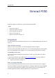
Simrad PI50 Simrad PI50 Study this chapter to familiarize yourself with the Simrad PI50. Topics • Important on page 8 • System description on page 9 • System diagram on page 10 • System units on page 11 • Support information on page 14 Important As with all other advanced instruments, there are a few important things that you must be aware of. When the PI50 is not used When you do not use the PI50, switch off the display and the computer. You may switch of the PI50 Sensor Receiver too.
Simrad PI50 System description The Simrad PI50 is designed for the professional fishery community implementing the latest innovations. The catch monitoring system allows you to stay in full control of the gear and its behaviour. The system is designed to be equally useful for all fishing types. Bottom trawlers, pelagic trawlers, purse or danish seiners - whatever kind of gear you use, all vessels can take advantage of the functionality provided by the PI50.
Simrad PI50 System diagram Figure 1 diagram System A basic system diagram is provided. Interface capabilities and power cables are not shown. A Display Unit B Processor Unit C Sensor Receiver D Power Supply E Hydrophone F Catch Monitoring Sensors Additional units include: • Sensor Battery Charger • Loudspeaker A loudspeaker is optional, and it must be installed if you wish to hear the audible alarms. Note that a loudspeaker can not be connected directly to the computer.
Simrad PI50 System units Each system unit is described in more detail. Colour display Any commercial colour display can be used with the Simrad PI50 system provided that the display meets the basic specifications. These specifications are: • Minimum screen resolution: 1280 x 1024 Processor Unit A dedicated maritime computer may be provided with the Simrad PI50 system. Figure 2 PI50 Marine Computer When this computer is supplied, it is readily set up with all necessary software.
Simrad PI50 • Memory: 2 Gb • Free hard disk space: 30 Gb • Chipset: Intel • Graphic adapter: DirectX9.0c compatible with Direct3d and OpenGL[2] • Interfaces: – One serial (RS-232) interface to communicate with the Receiver Unit Note that “PCI Express” serial interface boards are not supported.
Simrad PI50 Hydrophone Two hull mounted hydrophones are available, one for purse seining operations, and one for trawl operations. You can install both, and then select active hydrophone by means of a selector box on the bulkhead. Purse seine hydrophone Figure 4 Purse seine hydrophone The hull mounted hydrophone for purse seining operations has a 90 degrees horizontal beam and a 30 degrees vertical beam to provide the PI50 with optimal reception from the sensors on a purse seine.
Simrad PI50 Catch monitoring sensors A large selection of sensors can be used with the PI50 system.
Simrad PI50 USA • Address: 19210 33rd Ave W, Lynnwood, WA 98036, USA • Telephone: +1 425 712 1136 • Telefax: +1 425 712 1193 • E-mail address: simrad.usa@simrad.com • Website: http://www.simrad.
Simrad PI50 Getting started This chapter describes how to get started with the basic operation of the PI50. Topics • Power On/Off procedures on page 16 • Using the trackball on page 17 • Sensor presentations on page 18 • Starting normal operation on page 19 • Title Bar on page 25 • The menu system on page 26 Power On/Off procedures Observe these procedures to switch the Simrad PI50 on and off. Power on This procedure explains how to power up the Simrad PI50.
Getting started The PI50 starts up using the same operational parameters as the last time you used it. If these parameters are acceptable, continue operation. If you wish to alter basic operational parameters, see the dedicated procedures. → Starting normal operation on page 19 Power off This procedure explains how to power off the Simrad PI50. Note You must never switch off the PI50 only by means of the on/off switch on the computer.
Simrad PI50 A standard computer mouse can also be used. If you wish to use a mouse, we recommend that you find one equipped with a control wheel. Sensor presentations The PI50 can be used with several different sensors, but only six sensors simultaneously. Figure 7 Sensor presentation example with sensor views and trend views shown When sensors are selected, the presentation of these are made automatically.
Getting started Starting normal operation Once you have powered up the complete PI50 system, you are ready to start the actual operation. When started up, the PI50 will automatically apply its previous setup parameters. These procedures are partly provided to get you acquainted with the basic functionality provided by the PI50, and partly to set up the system for normal use. If you already know the PI50, or the current parameters are acceptable, you do not need to carry out the procedures.
Simrad PI50 2 Click the User Settings button to open the User Settings dialog. 3 In the User Settings dialog, click one of the factory settings in the top text field: 4 • Simrad Factory Default • Simrad Purse Setup • Simrad Trawl Setup Click the Activate Selected Setting, then click Close. How to select and set up the sensors The PI50 allows you to put the entire PI sensor range to use.
Getting started 8 In the Select Sensors dialog, observe the items in the Selected Sensors list. Note The order of the sensors in this list is also reflected to the order of the sensor view rectangles → 9 How to control the order of the sensor views on page 71 Click once a sensor type to select it. 10 Click one of the [▲] or [▼] buttons to move the sensor up or down on the list in the Selected Sensors field.
Simrad PI50 C Choose Update Rate. a Update Rate This parameter i used to select the sensor’s update rate. This is how often the PI50 can expect to receive information from the sensor. Note The Update Rate parameter is vital. The update rate you choose here must comply to the update rate programmed into the sensor. If these do not match, the communication will not work. D E The default update rates for the various sensors are listed in chapter PI50 Sensors.
Getting started F Observe the Offset value. a Offset Sensors measuring spread and depth can have an offset value. The offset value for the depth sensors are determined during calibration. → How to calibrate the depth sensors on page 24 The offset value for the spread sensor must be entered manually based on your knowledge about the physical locations of the sensors and the properties of the gear. 13 Click Apply to save the sensor configuration.
Simrad PI50 How to calibrate the depth sensors Only depth sensors can be calibrated. The purpose is to make sure that the depth reported by the sensor is as accurate as possible. This procedure is carried out on board the vessel. Note In order to calibrate the sensor, it must be submerged in salt water. The software provided for calibration assumes that the sensor is lowered to 1 meter deep.
Getting started Title Bar The PI50 Title Bar is located on the top of the display presentation, and it is stretched from the far left to the far right side. The Title Bar provides buttons to hide or show the menu, to make a screen capture, to open the Messages dialog, and to open the context sensitive on-line help. It also provides navigational information, as well as a few buttons related to operating system features. For more detailed information about the Title Bar, see chapter Display views.
Simrad PI50 The menu system This section provides a short introduction to the menu system, and explains the basic use of the PI50 menu buttons. For more information about the menu system, see The menu system on page 106. Topics • The menu hierarchy on page 26 • Menu buttons on page 26 The menu hierarchy Figure 9 The Main menu (top) with the Operation sub-menu below The menu system on the PI50 is by default placed on the right hand side of the display presentation.
Getting started How to select a numerical parameter using the +/- buttons 1 Move the cursor to either side of the button, and observe that the background colour changes. a Click on the left side of the button to decrease the numerical value. b Click on the right side of the button to increase the numerical value. How to select a numerical parameter by moving the cursor horizontally 1 Place the cursor on the middle of the button. 2 Click and hold the left mouse button depressed.
Simrad PI50 How to select a parameter using a sub-menu 1 Click the middle section of the button to open a sub-menu, then click the requested parameter value. The chosen value is applied, and the sub-menu is automatically closed. 2 Whenever applicable, you can also access the sub-menu by clicking the left and right side of the button, but this method will not show you the menu choices. a Click on the left side of the button to select a lower sub-menu choice.
Display views Display views The display views provided by the Simrad PI50 are based on the award winning design of the Simrad ME70 multibeam echo sounder. The menu system, presentation of data in the operational modes, and the user interface elements, have been created in close cooperation with designers and users. This chapter provides a brief overview of the information displayed by the Simrad PI50, and how the information is organised.
Simrad PI50 Display organisation A typical PI50 system display presentation is shown. Figure 10 A Sensor presentation example with sensor views and trend views shown Title Bar The Title Bar identifies the logo, and provides several icons and buttons. These are used to hide or retrieve the menu system, and to enable basic system functions. → B Title Bar on page 33 Sensor views The sensor views are automatically placed on top of each other.
Display views D Main menu The Main menu is by default located on the right hand side of the presentation. To open any of the sub-menus, click the icons. To hide or retrieve the Main menu, click the Menu button on the Title Bar. → E Menu system on page 32 Sub-menus Three sub-menus may be opened from the three icons in the bottom of the Main menu.
Simrad PI50 Menu system Figure 11 The Main menu (top) with the Display menu below The PI50 menu is located at the right side of the display. A detailed breakdown of the commands and parameters available from the menu system is given in the Menu system chapter. → The menu system on page 106 You can place the menu on the left side of the PI50 presentation by means of the Menu on the right side option in the Display Options dialog. You can also hide the menu from view if you do not need it.
Display views Title Bar The PI50 Title Bar is located on the top of the display presentation, and it is stretched from the far left to the far right side. The Title Bar provides buttons to hide or show the menu, to make a screen capture, to open the Messages dialog, and to open the context sensitive on-line help. It also provides navigational information, as well as a few buttons related to operating system features.
Simrad PI50 Operation buttons Menu button Click once on the Menu button to hide the menu, and one more time to bring it back again. When the menu is hidden, it will temporarily be shown on the left or right hand side of the display if you move the cursor to that position. → The menu system on page 106 Screen capture button Click this button once to create a screen capture of the current echogram presentation. To view the recorded image, click Screen Capture on the Taskbar to open the image browser.
Display views Vessel speed Provided that a GPS or speed log system is connected to the PI50, this field on the Title Bar will display the vessel’s current speed. The communication with the external GPS system or speed sensor is set up using the Navigation button on the Setup menu. Water temperature Provided that a temperature sensor is connected to the PI50, this field on the Title Bar will display the water temperature. Note This functionality is not implemented in the current SW version.
Simrad PI50 Minimize button Click this button to minimize the PI50 display presentation. This is an operating system function. To restore the presentation to its previous size, click the PI50 button on the operating system’s taskbar. Resize button Click this button to change the size of the PI50 display presentation. This is an operating system function. To restore the presentation to its previous size, click one more time on the Resize button. Exit button Click this button to close the PI50 program.
Display views Sensor views Each sensor providing information to the PI50 system uses a dedicated rectangle – a Sensor view – to display this information. These rectangles are dynamic. This means that you can change their size. The text font and the amount of information in the rectangle will change as the rectangle is made larger or smaller. All the size adjustments are made autom,atically depending on how many sensors you have in use, and how much information you wish to see.
Simrad PI50 Figure 13 Bottom Contact sensor view A Sensor identifier: The identifier is the Label ID parameter, the sensor name is the Sensor Value Name parameter. You can control these parameters in the Select Sensors dialog. B Bottom contact status icon: The arrow displays “bottom contact”. This is graphically represented by making contact with the horizontal black line (seabed). When bottom contact is lost, the arrow will rise from the seabed and change appearance.
Display views To monitor the filling rate, we recommend that you use minimum two sensors. Place the first sensor at the far end of the cod-end, it will tell you that the trawl is actually fishing. Place the second sensor closer to the trawl opening. Once the trawl is filled to the chosen location, the sensor is engaged, and you know that it is time to haul. Figure 14 Catch sensor view A Sensor identifier: The identifier is the Label ID parameter, the sensor name is the Sensor Value Name parameter.
Simrad PI50 • On a bottom trawl, you will use the sensor to achieve full control when shooting, and to position the trawl on the slope. • During pelagic trawling, you know how important it is to position the trawl relative to the largest concentration of fish. By using a PI Depth sensor, you can monitor the exact depth relative to the surface, and adjust the trawl depth accordingly. Additional depth sensors on the doors will monitor if the doors stay at the same depth.
Display views E Pulse lamp and Trend view icons: The green Pulse lamp icon flashes every time a signal is received from the sensor. Click the Trend view icon to open (and close) the Trend view for the sensor. PI Depth vertical geometry sensor view The vertical geometry view is created if you have one Depth sensor on each trawl door. The PI50 will then calculate the difference. Any type of Depth sensor will do.
Simrad PI50 • On a pelagic trawl, place the sensor behind the footrope. You will then know at once if the trawl approaches the bottom. If you use a second sensor behind the headrope, the difference between the two measurements will give you the height of the trawl opening. The sensor contains a small echo sounder to measure the height above the bottom. Figure 18 A PI Height sensor view Sensor identifier: The identifier is the Label ID parameter, the sensor name is the Sensor Value Name parameter.
Display views PI Spread sensor view The purpose of the Simrad PI Spread sensor system is to measure the distance between the two trawl doors. The PI Spread sensor will always require a PI Remote sensor on the other door to carry out this measurement. The PI Spread sensor system has been developed to be used on both bottom and pelagic trawls. • Use a PI Spread sensor on the port door and a PI Remote sensor on the starboard door. • The two sensors communicate using a special transverse acoustic link.
Simrad PI50 History field: When the size of the presentation rectangle permits, a history field D is shown. The field offers a graphical presentation of the sensor information for the last 20 minutes. The vertical range is set automatically defined by the current measurements. E Pulse lamp and Trend view icons: The green Pulse lamp icon flashes every time a signal is received from the sensor. Click the Trend view icon to open (and close) the Trend view for the sensor.
Display views A Sensor identifier: The identifier is the Label ID parameter, the sensor name is the Sensor Value Name parameter. You can control these parameters in the Select Sensors dialog. The colour code is issued automatically by the PI50 system. The same colour is used in the Trend view and in the History field. B Total spread: This the current distance between the two outer trawl doors as measured by the sensor. The current measurement unit is shown, as well as two blue arrowheads.
Simrad PI50 The PI Spread/Depth sensor thus contains both a pressure sensor to measure the water depth, and a spread sensor to measure the distance to the Remote sensor on the other trawl door. The PI Spread/Depth sensor has been developed to be used on both bottom and pelagic trawls. The sensor is normally installed on the port trawl door using an adapter. Three sensor versions are available. These are set up for maximum depth 300 m, 600 m or 1000 m.
Display views C Spread changes: This digit shows the spread distance changes recorded by the sensor, and thus the increasing or decreasing distance between the two trawl doors. The value is shown in units per minute. The direction is shown with the blue triangles. If the sensor does not detect any spread changes, the arrows are removed. D History field: When the size of the presentation rectangle permits, a history field is shown.
Simrad PI50 Figure 22 A PI Spread sensor view Sensor identifier: The identifier is the Label ID parameter, the sensor name is the Sensor Value Name parameter. You can control these parameters in the Select Sensors dialog. The colour code is issued automatically by the PI50 system. The same colour is used in the Trend view and in the History field. B Current temperature: This the current temperature measured by the sensor. The current measurement unit is shown, as well as a blue triangle.
Display views Note This is a “dual” sensor. It will seize two communication channels on the PI50. Figure 23 A B C D E F PI Temperature/Depth sensor view Sensor identifier: The identifier is the Label ID parameter, the sensor name is the Sensor Value Name parameter. You can control these parameters in the Select Sensors dialog. The colour code is issued automatically by the PI50 system. The same colour is used in the Trend view and in the History field.
Simrad PI50 G Temperature changes: This digit shows temperature changes recorded by the sensor. The value is shown in units per minute. The direction of the temperature change is shown with the blue triangle. If the sensor does not detect any temperature changes, the arrow is removed. H History field: When the size of the presentation rectangle permits, a history field is shown. The field offers a graphical presentation of the sensor information for the last 20 minutes.
Display views Figure 24 A B C D E PI Geometry sensor view (dual channel) Sensor identifier: The identifier is the Label ID parameter, the sensor name is the Sensor Value Name parameter. You can control these parameters in the Select Sensors dialog. The colour code is issued automatically by the PI50 system. The same colour is used in the Trend view and in the History field. Geometry icon: This icon provides the current status of your trawl geometry.
Simrad PI50 F Port length: This is the length of the wire between the headrope and the port Mini-R transponder. The current measurement unit is shown, as well as two blue arrowheads. These arrowheads indicate the current horizontal length changes. If the two arrowheads are pointing towards each other, the distance is decreasing. G Starboard length: This is the length of the wire between the headrope and the starboard Mini-R transponder.
Display views Note The PI Geometry Differential (DF) sensor versions are both “single” sensors. The other PI Geometry versions are all “dual” sensors. They will seize two communication channels on the PI50. Figure 25 PI Geometry Differential sensor view (single channel) 4: Geometry Diff (GD) 8 .3 A B C D E 350 m -50 (CD0121 15-034) Sensor identifier: The identifier is the Label ID parameter, the sensor name is the Sensor Value Name parameter.
Simrad PI50 PI Height/Depth sensor view The purpose of the Simrad PI Height/Depth dual sensor is to achieve accurate measurements of both the water depth and the distance from the sensor and down to the bottom. The PI Height/Depth sensor thus contains both a pressure sensor to measure the water depth, and a small echo sounder to measure the height above the bottom. The PI Height/Depth sensor has been developed to be used on both bottom and pelagic trawls.
Display views C D E F G H The two arrowheads indicate the current vertical movement of the sensor; up or down. In this example the sensor is slowly increasing with 5 meters each minute. If the two arrowheads are pointing towards each other, the height is decreasing. If they are pointing away from each other, the height is increasing. Height changes: This digit shows height changes recorded by the sensor. The value is shown in units per minute. The direction is shown with the two blue arrowheads.
Simrad PI50 Note This is a “dual” sensor. It will seize two communication channels on the PI50. Figure 27 A PI SeineSounder sensor view Sensor identifier: The identifier is the Label ID parameter, the sensor name is the Sensor Value Name parameter. You can control these parameters in the Select Sensors dialog. The colour code is issued automatically by the PI50 system. The same colour is used in the Trend view and in the History field.
Display views F Current depth: This the current depth measured by the sensor. The current measurement unit is shown, as well as a blue arrowhead. The arrowhead indicates the current vertical movement of the sensor; up or down. In this example the sensor measures 82,5 meters from the sea surface and down to the sensor, and the sensor – and thus the gear – is slowly rising with 3 meters each minute.
Simrad PI50 Place the sensor on the trawl belly behind the footrope, and use it to detect if the trawl is damaged by rocks or other items on the bottom. If this is detected, you can immediately adjust the gear to minimise the damage. Figure 29 Catch sensor view The PI Rip sensor is regarded – and must be set up – as a PI Catch sensor.
Display views Trend views The Trend view is opened by clicking the icon in the top right corner of the Sensor view rectangle. The view comprises a graph. The graph displays the historic development of the information provided by the sensor. Once opened, the graph is placed on the left side of the screen. If more than one graph is opened, they are placed on top of each other, in the order you open them. The vertical size of each graph is automatically adjusted.
Simrad PI50 PI Depth trend view Figure 32 PI Depth trend view The PI Depth trend view shows the depth values recorded by the sensor. a The vertical scale is defined by the settings made with the Range and Start Range buttons on the Main menu. b The horizontal scale is defined by the parameter selected in the Trend History Length button on the Display menu. The time can be selected from 5 to 1440 minutes (24 hours).
Display views PI Spread trend view Figure 34 PI Spread trend view The PI Spread trend view shows the distance between the trawl doors. a The vertical scale is defined by the settings made with the Range and Start Range buttons on the Main menu. b The horizontal scale is defined by the parameter selected in the Trend History Length button on the Display menu. The time can be selected from 5 to 1440 minutes (24 hours).
Simrad PI50 PI Spread/Depth trend view El PI de Distancia/Profundidad Maestro proporciona dos presentaciones de tendencias separadas, una para la distancia y una para la profundidad.
Display views PI Geometry trend view Figure 37 PI Geometry trend view The PI Geometry provides two trend views that can be opened individually. The shows the distance between the centre of the trawl and the two trawl doors. The top graph provides an overall description of the geometry. The bottom graph presents a more detailed view of the two distances that are measured by the sensor. A The vertical scale is defined by the settings made with the Range and Start Range buttons on the Main menu.
Simrad PI50 PI Remote/Depth trend view The PI Remote/Depth provides a depth graph. For information, see: → PI Depth trend view on page 60 PI Rip trend view The PI Rip provides a catch graph.
Display views Screen captures The PI50 provides a built-in screen capture function. To save all the information on the complete screen, click the Screen Capture button on the Title Bar. To access the images, click Screen Captures on the Display menu. This will open a file folder, and you can use standard operating systems to delete, copy, rename or move the files.
Simrad PI50 Operational procedures This chapter contains several operational procedures explaining how you can put your Simrad PI50 to use. Menu navigation employed by Simrad PI50 is similar to the other Simrad applications which follow the user interface standards developed by Simrad. The main menu is normally located at the right side of the screen, and by means of dedicated icons at the bottom of the main menu, you can open the relevant sub-menus or dialogs.
Operational procedures User settings The PI50 allows you save an unlimited number of user settings [4]. All parameters you have entered to set up the PI50 to suit your preferences are then saved, and you can use any name - including your own - to identify the saved settings. Whenever required, you can retrieve these settings, and continue your work. To reset the entire PI50, you can also retrieve the factory default settings.
Simrad PI50 How to use previously saved settings If you have saved sensor configurations dedicated for different gears or different tasks, you can retrieve these for fast and efficient parameter setup. 1 Observe the Main menu. It is normally located on the right hand side of the PI50 presentation. 2 Click the User Settings button to open the User Settings dialog. 3 In the User Setting dialog, click once on the requested saved settings in the Saved Settings list. 4 Click Activate Selected Setting.
Operational procedures User preferences This section provides procedures related to user preferences and individual customising.
Simrad PI50 1 Click the Display icon under the Main menu to open the Display menu. → Display menu on page 111 2 Click the middle of the Palette button, and observe the choices. 3 Click the palette you wish to use. The changes are made immediately. How to choose screen brightness This procedure explains how to reduce the intensity of the light emitted from the display. When the bridge is dark, the light emitted by the PI50 display can affect your night vision.
Operational procedures 3 Make the necessary adjustments. 4 Click OK to save the current settings and close the dialog. How to control the order of the sensor views You can control the vertical order of the Sensor view rectangles. This is configuration is made in the Select Sensors dialog. 1 Click the Setup icon under the Main menu to open the Setup menu. → Setup menu on page 112 2 Click the Select Sensors button to open the Select Sensors dialog.
Simrad PI50 How to select and set up the sensors This section provides the procedures to set up the various PI sensors supported by the PI50. A generic procedure is offered, as well as separate procedures for each sensor type. All sensors are set up using the Select Sensors dialog.
Operational procedures 3 Click the Select Sensors button to open the Select Sensors dialog. 4 Observe the Available Sensors field on the upper left side of the dialog. It lists all the sensor types supported by the PI50. 5 Click once a sensor type to select it. 6 Click the [►] button to copy the chosen sensor to the Selected Sensors list. 7 Repeat to select all requested sensors. The PI50 system will keep track of the quantity of sensors you are adding to the Selected Sensors list.
Simrad PI50 B Choose Label Name. • Label Name By default, the Label Name is the same as the sensor name listed with the Available sensors. Click in the field to enter another name. If you do not have a computer keyboard connected to your PI50 system, click the Keyboard button to open an on-screen keyboard. The Label Name is only shown in this dialog. C Choose Update Rate. a Update Rate This parameter i used to select the sensor’s update rate.
Operational procedures E Choose Channel Number. a Channel Number This is the communication channel used between the sensor and the PI50 system. Note The Channel Number parameter is vital. The communication channel number you choose here must comply to the channel number programmed into the sensor. If these do not match, the communication will not work. By default, the channel number will match the factory setting.
Simrad PI50 3 Observe the Available Sensors field on the upper left side of the dialog. It lists all the sensor types supported by the PI50. 4 Click once on the Bottom Contact sensor in the list, then click the [►] button to copy the sensor to the Selected Sensors list. 5 Observe that an error message appears if you try to add too many sensors to the Selected Sensors field. The PI50 can handle maximum six sensors. Remember that dual sensors each seize two communication channels.
Operational procedures 1 Click the Setup icon under the Main menu to open the Setup menu. Setup menu on page 112 → 2 Click the Select Sensors button to open the Select Sensors dialog. 3 Observe the Available Sensors field on the upper left side of the dialog. It lists all the sensor types supported by the PI50. 4 Click once on the Catch sensor in the list, then click the [►] button to copy the sensor to the Selected Sensors list.
Simrad PI50 How to set up the PI Depth sensor This procedure explains how to set up the PI Depth sensor for use. Note This procedure is also used to set up the PI Remote/Depth sensor. 1 Click the Setup icon under the Main menu to open the Setup menu. 2 → Setup menu on page 112 Click the Select Sensors button to open the Select Sensors dialog. 3 4 5 6 7 8 78 Observe the Available Sensors field on the upper left side of the dialog. It lists all the sensor types supported by the PI50.
Operational procedures The offset for the sensor is calculated automatically by means of the calibration procedure. If you already know the offset value, you can enter it directly. → How to calibrate the depth sensors on page 92 Note It is very important that the Channel number and Update Rate parameters defined for each sensor in the Select Sensors dialog matches the corresponding parameters programmed into the sensor.
Simrad PI50 7 8 Click one of the [▲] or [▼] buttons to move the sensor up or down on the list in the Selected Sensors field. The order in this list also controls the order in which the sensors are presented in the Sensor Configuration field, as well as the vertical order of the sensor view rectangles in the PI50 display presentation.
Operational procedures 4 Click once on the Spread sensor in the list, then click the [►] button to copy the sensor to the Selected Sensors list. Two Spread versions are available. These are set up for standard or extended (XT) spread range. This configuration can be changed in the PI Configurator utility. 5 Observe that an error message appears if you try to add too many sensors to the Selected Sensors field. The PI50 can handle maximum six sensors.
Simrad PI50 11 If this is the only sensor you wish to set up, or the last sensor, click Ok to save the settings and close the dialog. Related topics • PI Spread sensor view on page 43 • PI Spread trend view on page 61 • How to set up the PI Spread sensor on page 80 • How to set up spread and depth sensors to measure vertical geometry on page 95 How to set up the PI Temperature sensor This procedure explains how to set up the PI Temperature sensor for use.
Operational procedures → e PI Temperature sensor view on page 47 Channel Number Note It is very important that the Channel number and Update Rate parameters defined for each sensor in the Select Sensors dialog matches the corresponding parameters programmed into the sensor. If these vital parameters do not match, you will not receive information from the sensor. 9 If this is the only sensor you wish to set up, or the last sensor, click Ok to save the settings and close the dialog.
Simrad PI50 7 8 Click one of the [▲] or [▼] buttons to move the sensor up or down on the list in the Selected Sensors field. The order in this list also controls the order in which the sensors are presented in the Sensor Configuration field, as well as the vertical order of the sensor view rectangles in the PI50 display presentation.
Operational procedures The DF (Differential) Geometry sensor setting will only use one channel on the PI system, but will not provided extended range. The Coarse or Fine settings are not defined by the sensor configuration, but in the PI menu system. On the PI44/54 systems the phrases Sensitive and Coarse are used. Note The PI Geometry Differential (DF) sensor versions are both “single” sensors. The other PI Geometry versions are all “dual” sensors. They will seize two communication channels on the PI50.
Simrad PI50 e The names you enter are shown in the Sensor views. → PI Geometry sensor view on page 50 Channel Number Note It is very important that the Channel number and Update Rate parameters defined for each sensor in the Select Sensors dialog matches the corresponding parameters programmed into the sensor. If these vital parameters do not match, you will not receive information from the sensor.
Operational procedures 7 Click one of the [▲] or [▼] buttons to move the sensor up or down on the list in the Selected Sensors field. The order in this list also controls the order in which the sensors are presented in the Sensor Configuration field, as well as the vertical order of the sensor view rectangles in the PI50 display presentation.
Simrad PI50 Note This is a “dual” sensor. It will seize two communication channels on the PI50. 1 Click the Setup icon under the Main menu to open the Setup menu. → Setup menu on page 112 2 Click the Select Sensors button to open the Select Sensors dialog. 3 Observe the Available Sensors field on the upper left side of the dialog. It lists all the sensor types supported by the PI50.
Operational procedures The offset for the spread sensor must be entered manually based on your knowledge about the sensor installation and the properties of the gear. You can enter a value between +99 and –99 meters. Note It is very important that the Channel number and Update Rate parameters defined for each sensor in the Select Sensors dialog matches the corresponding parameters programmed into the sensor. If these vital parameters do not match, you will not receive information from the sensor.
Simrad PI50 5 Observe that an error message appears if you try to add too many sensors to the Selected Sensors field. The PI50 can handle maximum six sensors. Remember that dual sensors each seize two communication channels. 6 In the Selected Sensors field, click once on a sensor to select it. 7 Click one of the [▲] or [▼] buttons to move the sensor up or down on the list in the Selected Sensors field.
Operational procedures How to set up the PI Rip sensor The PI Rip sensor is set up as a PI Catch sensor.
Simrad PI50 Sensor presentation procedures This section provides the procedures to calibrate sensors, reset timers, apply filters and set up special presentations.
Operational procedures 6 Click the Setup icon under the Main menu to open the Setup menu. → Setup menu on page 112 7 Click Calibration. 8 In the Calibration dialog, click Start Calibration. 9 Wait for the PI50 system to do the calibration. When the Calibration dialog closes, the calibration has finished. Click Close to close the dialog. 10 Observe the numerical presentation of the sensor depth, and verify that it reads 1 m. 11 Retrieve the sensor from the water.
Simrad PI50 1 Click the Setup icon under the Main menu to open the Setup menu. → Setup menu on page 112 2 Click Receiver to open the Receiver dialog. 3 Change the status of the Catch/Bottom Filter. 4 Click OK to save the current settings and close the dialog. How to smooth out the data reception The Sensor Filter can be used if you have problems with the reception. It will average the data received from the sensors. The PI50 is designed to quickly update data.
Operational procedures How to remove noise from the sensor data The Multipath Filter is designed to remedy for reflections, spikes and time-lag in the sensor data. These problems may occur if neighbouring channels are used, or if the PI50 is disturbed by other hydroacoustic systems in use on own or other vessels. When you operate in areas with substantial reverberation due to the bottom conditions, or in shallow waters, you may experience “jumps” or spikes in the data received from the sensors.
Simrad PI50 Figure 39 Vertical geometry measurements Provided that the sensors are mounted on the trawl doors, the vertical geometry measurements can be made using any of the following sensors: • PI Depth • PI Height/Depth • PI Spread/Depth • PI Remote/Depth • PI Temperature/Depth The configuration of the vertical geometry measurement is made in the Select Sensors dialog during the configuration of a PI Spread sensor. Note You must have one depth sensor on each trawl door to measure vertical geometry.
Operational procedures How to set up depth and height sensors to measure total water depth If you have both a depth sensor and a height sensor mounted on the gear, you can make the PI50 calculate the total depth. The system will then read each of the two sensor values, add one to the other, and show you the sum. The configuration of the water depth measurement is made in the Select Sensors dialog during the configuration of a PI Depth sensor. Note You must have both sensors on you gear.
Simrad PI50 Receiver settings This section provides procedures related to receiver sensitivity, interference and receiver filters. Topics • How to adjust the receiver sensitivity on page 98 • How to fight interference on page 99 How to adjust the receiver sensitivity The parameter used to adjust the receiver sensitivity is the Detection Threshold (DT). It is adjusted in the Receiver dialog.
Operational procedures During special operations where extreme range is required, and the interference sources are minor, the parameter may be set to 8. If interference is present, the parameter can by increased up to maximum 14. • 15 to 20: By increasing the parameter value, the threshold level is decreased. This is the main parameter range to be used with the PI50. The default value for the detection threshold is 17. 4 Click OK to save the current settings and close the dialog.
Simrad PI50 Alarms and messages This section provides procedures related to alarms and messages generated by the PI50. Topics • How to read and acknowledge alarms and messages on page 100 • How to set up sensor alarms on page 100 • How to access the log files on page 101 How to read and acknowledge alarms and messages Messages could be related to any type of hardware or software error, and even events related to operational conditions.
Operational procedures Each sensor has an individual alarm setting. To enable an alarm, you must define minimum and maximum limits within the sensor’s range, and click to enable message and/or audio notification. [5] If the alarm is triggered, an audible signal may thus be provided, and/or you will receive a message indicating which sensor that caused the alarm. Once an alarm has been triggered, it is automatically disabled after 20 seconds.
Simrad PI50 This procedure assumes that you are familiar with the Microsoft® XP® and/or Microsoft® 7 operating system utilities for file handling. 1 Click the Display icon under the Main menu to open the Display menu. → 2 Display menu on page 111 Click Screen Captures to open an operating system folder.
Operational procedures Software procedures The purpose of this information is to guide you through the required tasks related to software installation and/or upgrading on the Simrad PI50. Software upgrades are useful if your PI50 fails, and you suspect a software error. An upgrade is also required whenever the PI50 software is modified. If the PI50 system is provided with a computer, it is delivered with all necessary software installed, configured and tested.
Simrad PI50 How to obtain the PI50 license The PI50 requires a valid license to operate. Without a license you will not be able to communicate with the PI50 Receiver. Note If you replace your computer, or if you replace major components inside your computer, you will need a new license code. We strongly advice you to record the license code for safe keeping. You may for example write it down in the beginning of the reference manual. 1 2 Double-click the PI50 icon on the desktop to start the application.
Operational procedures Unless you have made any hardware changes on your computer, the existing software license will be used. How to remove the PI50 software You may wish to remove the PI50 software from your computer. 1 Observe the operating system’s functionality for software removal.
Simrad PI50 The menu system Menu navigation employed by the PI50 is similar to the other Kongsberg Maritime applications which follow the new user interface standards developed by Kongsberg Maritime. The main menu is by default located at the right side of the screen. By means of dedicated icons at the bottom of the main menu, you can open and close the relevant sub-menus. Menu choices shown in dark colours are not available for the current operation or operational mode.
The menu system Figure 41 Sub-menu icons From left: • Operation menu • Display menu • Setup menu Button types Each menu contains several menu buttons. Each button shows the function of the button, some of them also display the current parameter setting. The majority of the buttons in each menu provide one or more of these functions: • You can increase and decrease parameter values by clicking the [+] and [–] fields on the button.
Simrad PI50 How to select a numerical parameter by means of the scroll wheel 1 Place the cursor on the middle of the button. 2 Spin the scroll wheel in either direction to increase or decrease the parameter value. 3 Release the scroll wheel when the requested value is shown. How to select a numerical parameter using the keyboard 1 Click the middle section of the button to open a text field. 2 Enter the numerical value into the text field.
The menu system Main menu The following functions and parameters are available from the Main menu. [6] 1 The User Settings dialog allows you to save the current user settings (parameter selections), and to retrieve previously saved factory or user settings. 2 The Range function allows you to specify the maximum range of the sensors related to physical length or depth measurements.
Simrad PI50 Operation menu The following functions and parameters are available from the Operation menu. Click once on the icon under the Main menu to open the Operation menu. Click one more time on the icon to close the menu. 1 2 3 4 110 The Sensor Filter can be used if you have problems with the reception. It will average the data received from the sensors. The default setting of the Sensor Filter is Light.
The menu system Display menu The following functions and parameters are available from the Display menu. Click once on the icon under the Main menu to open the Display menu. Click one more time on the icon to close the menu. The Palette function allows you to change the main colour scheme of the PI50 presentation. 2 The purpose of the Screen Brightness function is to adjust the intensity of the light given off by the display.
Simrad PI50 Setup menu The following functions and parameters are available from the Setup menu. Click once on the icon under the Main menu to open the Setup menu. Click one more time on the icon to close the menu. 8 112 1 The Simulator will provide artificial data to support hands-on PI50 training. 2 The Gear Type function allows you to set up the PI50 to work with either a pelagic or a bottom trawl. 3 The Select Sensors dialog allows you to define which sensors you will use to monitor your gear.
Index Index A About this manual, 7 Access log files, 101 message files, 101 Acknowledge all Messages, 100 Alarm procedures, 100 Alarm Limits description, 101 procedure, 100 Alarms read and acknowledge, 100 Apply user settings procedure, 68 B Bottom Contact sensor view, 38 trend view, 59 Bottom Contact sensor setup, 75 Button language procedure, 19, 69 Buttons Display menu, 111 Main menu, 109 Operation menu, 110 Setup menu, 112 C Calibration procedure, 24, 92 Catch sensor view, 39 trend view, 59 Catch sen
Simrad PI50 access log files, 101 access message files, 101 adjust interference measures, 99 adjust receiver sensitivity, 98 calibrate Depth sensors, 24, 92 change palette, 69 change screen brightness, 70 change units, 70 choose language, 19, 69 configure sensors, 72 control the order of the sensor views, 71 define alarm limits, 100 install software, 103 introduction to procedures, 66 obtain PI50 software license, 104 power off PI50, 17 power on PI50, 16 read and acknowledge messages, 100 reduce display in
Index setup, 76 trend view, 59 PI de Distancia/Profundidad Maestro presentación de tendencia, 62 PI Depth purpose, 39 sensor view, 40 setup, 78 trend view, 60 PI Geometry purpose, 50, 52 sensor view, 51 setup, 84 trend view, 63 PI Geometry Differential sensor view, 53 PI Height purpose, 41 sensor view, 42 setup, 79 trend view, 60 PI Height/Depth purpose, 54 sensor view, 54 setup, 86 trend view, 63 PI Remote purpose, 43 PI Remote/Depth purpose, 57 trend view, 64 PI Rip purpose, 57 trend view, 64 PI SeineSou
Simrad PI50 R Read vertical geometry procedure, 97 Receiver sensitivity procedure, 98 Receiver Unit description, 12 Reflections remove, 95 Remote sensor purpose, 43 Remote/Depth trend view, 64 Remote/Depth sensor purpose, 57 Removal software, 105 Remove noise procedure, 95 Remove reflections procedure, 95 Remove spikes procedure, 95 Remove time-lag procedure, 95 Reset counters procedure, 93 Rip trend view, 64 Rip sensor purpose, 57 S Save user settings procedure, 23, 67 Screen brightness procedure, 70 Sei
Index PI Temperature, 62 PI Temperature/Depth, 62 PI Twin Spread, 61 Twin Spread sensor view, 45 trend view, 61 Twin Spread sensor purpose, 44 setup, 89 U Units main, 9 procedure, 70 system, 11 Update Rate Select Sensors, 22, 74 Upgrade software, 104 User preferences procedures, 69 User settings how to save, 23, 67 procedure, 68 procedures, 67 V Vertical geometry procedure, 97 sensor view, 41 set-up procedure, 95 Visual presentation procedure, 69 W Warning read and acknowledge, 100 328457/A 117
©2010 Kongsberg Maritime