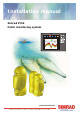
Installation manual Simrad PI54 Catch monitoring system www.simrad.
851-165187 / Rev.A Simrad PI54 Catch monitoring system Installation manual NOTICE Operation of the PI54 system assumes that the communication between the Operator Unit and the sensors is fully functional. Ensure that the communication channels defined on the Operator Unit matches those of the sensors.
About this document Rev Date Written by Checked by Approved by Rev.A 07.06.05 RBr KR KR Original issue. © 2005 Simrad AS ISBN 82-8066-060-7 All rights reserved. No part of this work covered by the copyright hereon may be reproduced or otherwise copied without prior permission from Simrad AS. The information contained in this document is subject to change without prior notice.
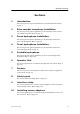
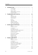
Installation manual Sections 1 Introduction This section provides a general introduction to the PI54 installation. Refer to page 1. 2 Echo sounder transducer installation This section provides general guidelines for the installation of the optional echo sounder transducer. Refer to page 18. 3 Purse hydrophone installation This section provides general guidelines for the installation of the PI54 purse seine hydrophone. Refer to page 42.
Simrad PI54 1 2 3 4 II INTRODUCTION . . . . . . . . . . . . . . . . . . . . . . . . . . . . . . . . . . . . . . . . . 1 System diagram . . . . . . . . . . . . . . . . . . . . . . . . . . . . . . . . . . . . . . . . . . Scope of supply . . . . . . . . . . . . . . . . . . . . . . . . . . . . . . . . . . . . . . . . . . Supply conditions . . . . . . . . . . . . . . . . . . . . . . . . . . . . . . . . . . . . . . . . General installation requirements . . . . . . . . . . . . . . . . . . . . . . . . . . .
Installation manual Installation drawings . . . . . . . . . . . . . . . . . . . . . . . . . . . . . . . . . . . . . . 5 6 PORTABLE HYDROPHONE . . . . . . . . . . . . . . . . . . . . . . . . . . . . . . . 120 Purpose . . . . . . . . . . . . . . . . . . . . . . . . . . . . . . . . . . . . . . . . . . . . . . . . 120 General guidelines . . . . . . . . . . . . . . . . . . . . . . . . . . . . . . . . . . . . . . . . Deployment over the side . . . . . . . . . . . . . . . . . . . . . . . . . . . . . . . . .
Simrad PI54 IV 851-165187 / Rev.
Introduction 1 INTRODUCTION The purpose of this manual is to provide the information and basic drawings required for installation of the Simrad PI54 catch monitoring system. These instructions must be followed carefully to ensure optimal system performance. As a guide, installation procedures are presented in the order they are to be performed. After installation, this document must be stored on board the vessel for later reference when updating or servicing the equipment.
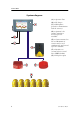
Simrad PI54 System diagram (A) = Operator Unit (B) = PI charger (C) = Hydrophone (provides communication with the sensors) (D) = Optional echo sounder transducer. Several types are available. (E) = Sensors mounted on the net. Maximum six sensors may be used simultanously, and several types are available. (F) = Interfaces to external sensors (serial lines, NMEA format) (G) = DC power input 2 851-165187 / Rev.
Introduction Scope of supply Main units The standard Simrad PI54 catch monitoring system is comprised of the following main units. All must be ordered separately.
Simrad PI54 Sensor Order number PI Twin Spread sensor PI3--206896 PI Remote 1 sensor PI3--206870 PI Remote 2 sensor PI3--206871 PI Remote 3 sensor PI3--206872 PI Remote 4 sensor PI3--206885 PI Temperature sensor PI3--207640 Sensor chargers In order to charge the PI54 sensor batteries, the following charger is available. 4 Sensor Order number PI Sensor charger LAD--207624 851-165187 / Rev.
Introduction Supply conditions The following supply conditions are applicable to standard Simrad PI54 deliveries and associated optional equipment. Equipment responsibility The shipyard performing the installation and/or dealer becomes fully responsible for the equipment upon receipt unless otherwise stated in the contract. The duration of responsibility includes: • The period of time the equipment is stored locally before installation. • During the entire installation process.
Simrad PI54 General installation requirements Responsibility and approval The Simrad PI54’s hydrophone and echo sounder installation must be approved on a case-by-case basis with regard to the vessel’s national registry and corresponding maritime authority. The shipowner and shipyard performing the installation are responsible for obtaining installation approval. Environmental requirements All equipment, unless otherwise specified, must be protected from temperature extremes and excessive humidity.
Introduction Equipment handling The units may be supplied as spare parts, or as parts of a delivery. Transportation Unless otherwise stated in the accompanying documentation, electronic, electro-mechanical and mechanical units supplied by Simrad can be transported using all methods approved for delicate equipment; (by road, rail, air or sea).
Simrad PI54 Heavy units may be equipped with lifting lugs for transportation by crane within the workshop or installation area. Before a crane is used, check: • The applicable weight certificate for the crane. • The security of the lifting lugs. Ensure that all available lifting lugs are used. Ensure the unit remains under control during the operation to avoid damage to the unit, equipment or personnel. Heavy units may be transported using a fork-lift truck.
Introduction - If any units are damaged, prepare an inspection report stating the condition of the unit and actions taken. Describe the damage and collect photographic evidence if possible. Re-preserve the equipment. - If the units are not damaged, check the humidity absorbing material. If required, dry or replace the bags, then repack the unit(s) according to the packing instructions. 7 If the crate has been opened, make sure that is it closed and sealed after the inspection.
Simrad PI54 Caution: Units containing lithium or alkaline batteries must be handled separately and with care. Such units are marked accordingly. Do not attempt to recharge such batteries, open them or dispose of them by incineration. Refer to the applicable product data sheets. Inspection and unpacking An inspection must be carried out immediately after the unit(s) have arrived at their destination. • Check all wooden or cardboard boxes, plastic bags and pallets for physical damage.
Introduction • Place the carton on a stable work bench or on the floor with the top of the carton uppermost. • In the absence of other instructions, always open the top of the carton first. The contents will normally have been lowered into the carton from above, so this will usually be the easiest route to follow. - Care must be used when opening the carton to ensure the contents are not damaged.
Simrad PI54 Note: Do not break the seal to open a circuit board package before the board is to be used. If the board package is returned to the manufacturers with the seal broken, the contents will be assumed to have been used and the customer will be billed accordingly. Assuming all is well, open the bag and remove the unit. Open the unit and check inside. Remove any packing and desiccant material that may be inside. Unpacking mechanical units Mechanical units may be heavy.
Introduction Once unpacked, the equipment must be kept in a dry, non condensing atmosphere, free from corrosive agents and isolated from sources of vibration. Note: Do not break the seal to open a circuit board package before the board is to be used. If the board package is returned to the manufacturers with the seal broken, the contents will be assumed to have been used and the customer will be billed accordingly.
Simrad PI54 • Open the unit, and using a vacuum cleaner, remove all dust etc. from the unit. Great care must be taken to ensure the circuit boards and modules are not damaged in the process. Mechanical units If a mechanical unit may have been exposed to a salt atmosphere while it was in use, it must be thoroughly cleaned both internally and externally to prevent corrosion. • If the construction materials and type of unit permits, wash the unit using a high-pressure hose and copious amounts of fresh water.
Introduction Internal batteries If the unit contains batteries, these may discharge slowly during storage. If the unit is to be stored for an extended period, disconnect or remove all internal batteries. A suitable piece of insulating material can be placed between the battery and the electrical contacts to prevent electrical discharge. The battery can then remain in the unit, reducing the risk of it being misplaced during the storage period.
Simrad PI54 ESD precautions Electro-Static Discharge (ESD) is the transfer of an electrostatic charge between two bodies at different electrostatic potentials, caused either by direct contact or induction by an electrostatic field. The passing of a charge through an electronic device can cause localised overheating, and it can also “puncture” insulating layers within the structure of the device. This may deposit a conductive residue of the vaporised metal on the device, and thus create a short circuit.
Introduction Temperature protection If the unit must be protected against extremes of temperature, the carton/crate must be lined on all walls, base and lid with 5 cm thick polyurethane or polystyrene foam. These units will be identified as delicate in the applicable documentation. The package must then be clearly marked: Note: Must not be transported or stored in temperatures below -5 degrees Celsius.
Simrad PI54 2 TRANSDUCER INSTALLATION Purpose Due to the fact that several transducer types may be used with the PI54 system, you will need to read the installation manual for the chosen transducer. The information provided in this chapter will only provide general information. Refer to the installation manuals provided with the transducers for more specific information. The PI54 can be used with maximum two transducers simultanously, one low frequency (38 or 50 kHz) and one high frequency (200 kHz).
Transducer installation Transducer location General A single answer to the question where to locate the transducer cannot be given. It depends very much on the vessel’s construction. However, there are some important guide lines. Go deep The upper water layers of the sea contain a myriad of small air bubbles created by the breaking waves. In heavy seas the uppermost 5 to 10 metres may be air-filled, with the highest concentrations near the surface.
Simrad PI54 Boundary water layer When the vessel forces its way through the sea, the friction between the hull and the water creates a boundary layer. The thickness of the boundary layer depends upon vessel speed and the roughness of the hull. Objects protruding from the hull, and dents in the hull, disturb the flow and increase the thickness of the boundary layer. The flow in this boundary layer may be laminar or turbulent. A laminar flow is a nicely ordered, parallel movement of the water.
Transducer installation Propeller noise The propulsion propeller is the dominant noise source on most fishing vessels, research vessels, merchant vessels and pleasure crafts. The noise is transmitted through the sea water. For this reason, the transducer should be placed far away from the propeller, which means on the fore part of the hull. Positions outside the direct line of sight from the propeller are favourable.
Simrad PI54 Summary and general recommendation Some of the above guide lines are conflicting, and each case has to be treated individually in order to find the best compromise. Generally the propeller noise is the dominant factor, and a recommended transducer location is in the fore part of the hull, with maximum distance from the bow equal to one third of the total length of the hull at the water line.
Transducer installation External mounting This transducer has a streamlined housing, and it is designed for installation outside the hull. This transducer is mainly used on smaller vessels. A location approximately 0.5 m aside from the keel may be adequate for the passage of water between the keel and the transducer. The figures illustrate external mounting of transducers on steel hulls and on wood or polyester hulls respectively.
Simrad PI54 Steel hull A fairing (A), made by the shipyard, is placed between the transducer and the hull. It is required in order to adapt for the deadrise angle of the hull, and it will also house a cable service loop (B). The fairing can be made of wood or steel, and should have the same outline dimensions as the transducer. Remember to create an air outlet (E) on the fairing, and to fill the bolt holes with a filling compound to ensure a smooth transducer surface.
Transducer installation Wood or polyester hull A fairing (A), made by the shipyard, is placed between the transducer and the hull. It is required in order to adapt for the deadrise angle of the hull, and will also house a cable service loop (B). The fairing is made from wood, polyester or steel, and should have the same outline dimensions as the transducer. Use tarred felt (H) between th fairing and the hull.
Simrad PI54 Flat hull If the vessel’s hull is flat you do not need a fairing. The transducer is then be bolted directly to the hull using two bronze or stainless steel bolts (I) and a cable bushing. Note that the cable bushing must be mounted with proper gaskets (4) under and over the hull, as well as sealing compound (J) around the its body. Also, fill the bolt holes with a filling compound to ensure a smooth transducer surface.
Transducer installation Longitudinal angle On deplacement hulls, the transducer (A) must be mounted in an angle of 5 to 8 degrees (B) in relation to the keel (C). With a planing hull, this angle must be 0 degrees. (A) = Transducer (B) = 5 to 8° on deplacement hulls, 0° on planing hulls (C) = Keel (F) = Forward 851-165187 / Rev.
Simrad PI54 Transducer blister With a transducer with circular housing, one recommended installation method is by using a blister. The transducer blister must be designed and manufactured by the installation shipyard to fit the vessel’s sixe and hull shape. Mounting and clamping rings Circular transducers may be provided with mounting and clamping rings, or with drawings to allow for local production of these.
Transducer installation Example: Large transducer The illustration below shows a typical transducer blister designed for a large transducer. Note that due to the physical size of the transducer, a U-shaped support bar (E) is used to support the transducer.
Simrad PI54 Example: Small transducer The illustration below shows a typical transducer blister designed for a small transducer. The same blister design principles as for a large transducer apply. (A) = Streamlined blister (E) = Air outlet (B) = Mounting ring (F) = Forward (C) = Clamping ring (G) = Transducer cable (D) = Guide Note that the transducer cable must be provided with a cable loop inside the blister. Observe the vertical forward edge of the blister.
Transducer installation Common guidelines The best performance is obtained with a blister height of 40 cm or more. A streamlined shape and rounded edges reduce the flow noise. A vertical leading edge or front will guide the aerated water to the sides of the blister. The orientation of the blister should follow the water flow. The interior of the blister must be filled with sea water. Use drainage holes in the bottom and an air outlet on the top.
Simrad PI54 Physical location The blister is placed on one of the sides of the hull, and the distance from the keel is a trade off between a close distance giving a turbulent flow of water in a narrow passage, and a large distance bringing the transducer higher up and also more affected by vessel roll. Normally a distance of approximately 1 m is a good compromise. Observe the horizontal and vertical distances (X and Y) between the keel and the transducer blister.
Transducer installation Box keel Vessels with a box keel may use this for transducer installation. The box keel is already the deepest part of the vessel. If the box keel is too narrow to accommodate the transducer, it can be widened, either symmetrically or to one side only. In the last case the installation could also be described as a blister merged into the keel.
Simrad PI54 Example The figure below illustrates a symmetrical box keel installation. (A) = Box keel (D) = Cable in steel conduit (B) = U-shaped support bar (E) = Cable service loop (C) = Stuffing tube 34 851-165187 / Rev.
Transducer installation Cable glands The transducer cable must pass through the hull using approved cable glands for the type of vessel in question. A steel cable gland is normally used on professional vessels with steel hulls. A bronze cable gland can be delivered as an option for vessels with wood or fibreglass construction. Vessel not to be classified can as an option use a cable gland made of plastic.
Simrad PI54 Cable gland installation for steel hulls This cable gland kit is designed for steel vessels. It must be welded to the hull plates. (A) = Steel conduit (B) = Stuffing tube, DNV approved carbon steel st52.3 (C) = Washers, 24 x 8 x 2 mm (D) = Rubber gasket (E) = Packing nipple.
Transducer installation Gland installation for wood or GRP hulled vessels A bronze cable gland kit is available for wood and GRP vessels. (A) = Packing nipple. Make sure that you do not damage the transducer cable by tightening the packing nipple too hard! (B) = Washers (C) = Rubber gaskets (D) = Hole diameter 28 mm (E) = Steel conduit (F) = Cable to the echo sounder (or a junction box) The gland gland kit includes all of the necessary parts needed to install the unit excluding screws.
Simrad PI54 Cable gland installation for smaller vessels This cable glands made of plastic is designed for those smaller vessels that do not need to be classified. (A) = Packing nut (bronze). Ensure that you do not to damage the transducer cable by tightening the packing nut too hard! (B) = Rubber gasket (C) = Plastic disk (D) = Rubber gasket (E) = Stuffing tube (F) = Backing nut (bronze) (G) = Backing washer (plastic) (H) = O-ring 42.5 x 3.0 N (I) = O-ring 39.5 x 3.
Transducer installation Cable in steel conduit It is strongly recommended to lay a steel conduit from the transducer’s cable gland to the echo sounder transceiver, and to pull the transducer cable through this conduit. There are two reasons for this. • First, it will make it easier at a later stage to replace the transducer. • Second, noise and interference from other electrical equipment is greatly reduced. With a steel conduit the installation will satisfy the EU regulations for EMC interference.
Simrad PI54 Handling and maintenance Do not lift the transducer by the cable. Some transducers are delivered with a cover plate on the face for protection during transport. Let this plate stay on as long as possible, but do not forget to remove it before the vessel goes into the sea. An anti-fouling paint may be applied to the transducer face. Because some paint types may be aggressive to the polyurethane in the transducer face, please consult Simrad’s list of approved paints on the next page.
Transducer installation Approved anti-fouling paints This is Simrad’s list of approved antifouling paints on polyurethane transducer housing. From Jotun Paints, Sandefjord Norway: • Antifouling Seamate HB 33 • Antifouling Seamate HB 66 • Antifouling Seamate HB 99 • Racing • Non-stop From International Paints: • Intersleek tie coat + 425 FCS - BXA386/BXA390/BXA391 Grey - HKA563/HKA570/HKA571 Yellow Mix BXA386, BXA390 and BXA391 first, then apply. When dry, mix HKA563, HKA570 and HKA571, apply.
Simrad PI54 3 PURSE SEINE HYDROPHONE Purpose The purpose of this chapter is to provide general guidelines for the installation of the PI54 hydrophone for purse seining.
Purse seine hydrophone installation Installation precautions Caution: 851-165187 / Rev.A The following precautions must be observed. Failure to do so can result in damage to the hydrophone which may render the PI54 catch monitoring system inoperative. 1 Observe the maximum allowable torque warning of 5 Nm when tightening the hydrophone studs. 2 Use only M8x35 socket countersunk head screws for mounting the hydrophone. 3 Secure threaded hydrophone hardware with Loctitet 270 or the equivalent.
Simrad PI54 Considerations Correct installation of the PI54 hydrophone is vital to the system’s performance. Several variables must be taken into consideration, the most important of which is the vessel’s construction. This guide is for use in selecting the best location for the hydrophone and includes a brief description of areas to be avoided. Note: Simrad strongly suggests that this information is read thoroughly, and that the instructions are understood and followed.
Purse seine hydrophone installation Boundary water layers: (A) = Turbulent flow (B) = Laminar flow (C) = Air bubbles in the water Air bubbles may also be introduced into the boundary layer. If the vessel’s hull has little flare and is relatively narrow, bubbles may escape to the sea surface without incident. On the other hand a wide, flat hull with minimal deadrise is prone to trapping air bubbles no matter how little flare it has.
Simrad PI54 Propeller noise A vessel’s main propeller is the dominant source of underwater acoustic noise. When ever possible, hydrophone(s) should be located as far a way as possible from the main propeller and never closer than ten meters. Hydrophone(s) should not be mounted in the direct acoustic path (line-of-sight) of the main propeller unless absolutely necessary.
Purse seine hydrophone installation When not in operation, bow/sternthruster tunnels create turbulence and hence underwater noise when a vessel is under way. Also, as a vessel pitches in heavy weather, thruster tunnels may fill with air or aerated water which can disturb hydrophone reception when released. Hydrophone installation should take into regard the noise and down stream disturbances found around and aft of thrusters.
Simrad PI54 Pre-installation check-list Choosing the optimal locations for hydrophones is not always easy, but decisions made at this phase of the installation process are critical to future system performance. Determining the best configuration for a given vessel often involves a compromise between contradicting requirements.
Purse seine hydrophone installation 851-165187 / Rev.A 13 Conduit used to run hydrophone cables in the interior of a vessel’s hull should extend well over its water line. 14 If you install both trawl and purse seine hydrophones, do not confuse the two types. The Trawl hydrophones are marked with order number 314-205250, while the Purse seine hydrophones are marked with order number 314-202275.
Simrad PI54 Optimal location of purse seine hydrophones The most influential factors effecting hydrophone reception common to most vessels are: • Noise from cavitation generated by the main propeller. • Air bubbles in the water around the hydrophone which impede acoustic signals. • Noise from other acoustic equipment mounted in close proximity.
Purse seine hydrophone installation Coverage area, orientation and tilt General Once the fore and aft placement of the purse seine hydrophone is decided, it is equally important to carefully consider its horizontal and vertical orientation. Hydrophone orientation can have a large influence on system performance. The hydrophone’s beam sensitivity is concentrated within a 90_ horizontal and -30_ vertical sector.
Simrad PI54 Figure 1 Horizontal coverage area The illustration shows a hydrophone installed at an angle of 70 degrees to the vessel’s center line. (A) = The PI54 hydrophone (B) = The horizontal coverage area Vertical coverage area The hydrophone has a vertical beam width of -30_ and should be tilted so that the most important part of the seine is adequately covered. Tilt should be no less than -15_ in most instances with the optimal tilt angle depending on the size (length/depth) of the seine in use.
Purse seine hydrophone installation Tilt angle The tilt angle is a function of net length and depth and may be estimated as follows: α = - [arctan (depth/length * π) - 15_+ β] α = tilt angle β = angle of heel (to port) after deploying the purse seine to starboard The following table gives some examples of recommended tilt angles for common size pure seines: Recommended tilt angles Net length/depth in meters 250 / 50 350 / 100 650 / 150 850 / 180 1500 / 200 2000 / 200 Recommended tilt angle * --15_
Simrad PI54 Mounting arrangement The PI54 purse hydrophone are delivered ready for installation in either freestanding or keel mounted shoes (which are to be built by the shipyard responsible for the installation). Several alternatives with corresponding detailed drawings have been included in this manual to cover the majority of installation options available.
Purse seine hydrophone installation Keel mounted shoes The hydrophone shoe may be keel mounted to avoid creating an appendage to the hull which may foul the purse wire. Keel mounted hydrophone shoe: (A) = Tilt angel (B) = Vertical coverage area (C) = Keel mounted hydrophone with fairing Should this solution be chosen, the following must be taken into consideration: • The hydrophone must have an unobstructed line-of-sight to the PI54 sensor(s) attached to the seine.
Simrad PI54 Free standing hydrophone in blister If there is no risk that hull protrusions will be fouled by the purse wire, mounting the hydrophone in a freestanding blister is a viable option. Free standing hydrophone in blister: (A) = Tilt angel (B) = Vertical coverage area (C) = Free standing hydrophone in blister (pipe diameter 200 to 250 mm) (1) = Approximately 400 mm, minimum 250 mm is required (2) = Must exceed 700 mm.
Purse seine hydrophone installation Dual hydrophone installation Large vessels and operations requiring a greater than normal coverage area can install two hydrophones with a vertical and horizontal overlap. Hydrophone selection is made with the help of a switch located in the wheelhouse.
Simrad PI54 Vertical coverage areas When the seine is normally located forward of the starboard beam when pursing the following information should be taken into consideration: • The optimal tilt angle for dual hydrophone installations is derived in the same manner as a for single hydrophone installations. Consult the section on Tilt angle for more information. • The hydrophones should be tilted so that the most important part of the seine is adequately covered.
Purse seine hydrophone installation Hydrophone protection Warning: Do not perform hot work near, paint, scrape, hit, pry, force, sandblast, high-pressure wash or otherwise subject hydrophones to excessive force. Installation precautions The following precautions must be observed. Failure to do so can result in damage to the purse seine hydrophone which may render the PI54 system inoperative.
Simrad PI54 Vessels operation in colder climates should weld steel fins and protection plates installed around hydrophones to protect them from being damaged by ice. Detailed drawing must be made specifically to suite each individual vessel in question and the installation performed by an authority with the expertise to do so. Surface protection Maintenance and replacement costs can be reduced if those parts of the hydrophone installation that are open to the sea are protected correctly.
Purse seine hydrophone installation Location and marking After installation, the location of hydrophones should be clearly marked on the vessel’s hull (above the water-line) directly over them. This information will help prevent hydrophone damage when dry-docking the vessel. It is very important to amend the docking-plans of larger vessels to also reflect this information so that blocks will not be placed in the vicinity of hydrophones, fins, deflection plates or other associated appendages.
Simrad PI54 Hydrophone cable The purse seine hydrophone is delivered with a 22 m cable. The cable is fitted with plug that fits the ANT socket on the rear side of the PI54 Operator Unit. General cable gland guidelines Hydrophone cables are passed through the hull using approved cable glands for the type of vessel in question. The standard delivery consists of a steel cable gland that is to be welded to the hull.
Purse seine hydrophone installation Cable gland installation for steel hulls The cable gland kit for steel vessels is included with standard deliveries. The drawing shows a single hydrophone, but normally a typical installation includes two hydrophones with respective cables spliced in a junction box and run to the wheelhouse in a conduit. Cable gland for steel hull vessels. (A) = Steel conduit (B) = Stuffing tube, DNV approved carbon steel st52.
Simrad PI54 Gland installation for wood or GRP hulled vessels A bronze cable gland kit is available for wood and GRP vessels. This kit is not included in the standard delivery, and must be ordered separately. The drawing shows a single hydrophone, but normally a typical installation includes two hydrophones with respective cables spliced in a junction box and run to the wheelhouse in a conduit. Cable gland for wood and GRP hulls. (A) = Packing nipple.
Purse seine hydrophone installation Cable gland installation for smaller vessels Cable glands made of plastic for those smaller vessels that do njot need to be classified are optional equipment for standard deliveries. This cable gland kit is not included in the standard delivery, and must be ordered separately. The drawing shows a single hydrophone, but normally a typical installation includes two hydrophones with respective cables spliced in a junction box and run to the wheelhouse in a conduit.
Simrad PI54 Splicing If you need to cut the cable, you must splice it correctly. Note: DO NOT solder the wires together with only electrical tape for insulation, as this will result in electrical noise and reduced operational performance. To splice the cable, use a metal junction box. The chassis of the junction box must be grounded, but the cable shielding must NOT be connected to the junction box ground.
Purse seine hydrophone installation Installation drawings Observe the following drawings. The drawings are also available on electronic format (DWG or PDF), consult your local dealer. 851-165187 / Rev.
Simrad PI54 PI54 Purse Seine hydrophone - Outline dimensions 68 851-165187 / Rev.
Purse seine hydrophone installation PI54 Purse Seine hydrophone - Cutout 851-165187 / Rev.
Simrad PI54 PI54 Purse Seine hydrophone - Keel mounted hydrophone, steel hull - Page 1 70 851-165187 / Rev.
Purse seine hydrophone installation PI54 Purse Seine hydrophone - Keel mounted hydrophone, steel hull - Page 2 851-165187 / Rev.
Simrad PI54 PI54 Purse Seine hydrophone - Keel mounted hydrophone, steel hull - Page 3 72 851-165187 / Rev.
Purse seine hydrophone installation PI54 Purse Seine hydrophone - Keel mounted hydrophone, wooden hull - Page 1 851-165187 / Rev.
Simrad PI54 PI54 Purse Seine hydrophone - Keel mounted hydrophone, wooden hull - Page 2 74 851-165187 / Rev.
Purse seine hydrophone installation PI54 Purse Seine hydrophone - Keel mounted hydrophone, wooden hull - Page 3 851-165187 / Rev.
Simrad PI54 PI54 Purse Seine hydrophone - blister installation on steel hull - Page 1 76 851-165187 / Rev.
Purse seine hydrophone installation PI54 Purse Seine hydrophone - blister installation on steel hull - Page 2 851-165187 / Rev.
Simrad PI54 PI54 Purse Seine hydrophone - blister installation on steel hull - Page 3 78 851-165187 / Rev.
Trawl hydrophone installation 4 TRAWL HYDROPHONE Purpose The purpose of this chapter is to provide general guidelines for the installation of the PI54 hydrophone for trawl.. Note: If your vessel shall be fitted for purse seine operations, DO NOT install the hydrophone(s) as explained in this chapter! Order numbers Trawl hydrophone, complete: HYD-205254 Trawl hydrophone, without cable gland: HYD-205826 Topics 851-165187 / Rev.
Simrad PI54 Installation precautions Caution: 80 The following precautions must be observed. Failure to do so can result in damage to the hydrophone which may render the PI54 catch monitoring system inoperative. 1 Observe the maximum allowable torque warning of 5 Nm when tightening the hydrophone studs. 2 Use only M8x35 socket countersunk head screws for mounting the hydrophone. 3 Secure threaded hydrophone hardware with Loctitet 270 or the equivalent. 4 Do not paint the hydrophone.
Trawl hydrophone installation Considerations Correct installation of PI54 hydrophone(s) is vital to system performance. Several variables must be taken into consideration, the most important of which is the vessel’s construction. This guide is for use in selecting the best location for the hydrophone and includes a brief description of areas to be avoided. Note: Simrad strongly suggests that this information is read thoroughly, and that the instructions are understood and followed.
Simrad PI54 Boundary water layers: (A) = Turbulent flow (B) = Laminar flow (C) = Air bubbles in the water Air bubbles may also be introduced into the boundary layer. If the vessel’s hull has little flare and is relatively narrow, bubbles may escape to the sea surface without incident. On the other hand a wide, flat hull with minimal deadrise is prone to trapping air bubbles no matter how little flare it has.
Trawl hydrophone installation Propeller noise A vessel’s main propeller is the dominant source of underwater acoustic noise. When ever possible, hydrophone(s) should be located as far a way as possible from the main propeller and never closer than ten meters. Hydrophone(s) should not be mounted in the direct acoustic path (line-of-sight) of the main propeller unless absolutely necessary.
Simrad PI54 When not in operation, bow/sternthruster tunnels create turbulence and hence underwater noise when a vessel is under way. Also, as a vessel pitches in heavy weather, thruster tunnels may fill with air or aerated water which can disturb hydrophone reception when released. Hydrophone installation should take into regard the noise and down stream disturbances found around and aft of thrusters.
Trawl hydrophone installation Drop keel In the event the vessel is equipped with a drop keel, the hydrophones should be mounted aft of it. The choice between installing a one, or two hydrophone system should be based on the same horizontal and vertical coverage requirements for vessels operating under similar conditions with fixed keels. 851-165187 / Rev.
Simrad PI54 Pre-installation check-list Choosing the optimal locations for hydrophones is not always easy, but decisions made at this phase of the installation process are critical to future system performance. Determining the best configuration for a given vessel often involves a compromise between contradicting requirements.
Trawl hydrophone installation 851-165187 / Rev.A 10 The hydrophone that is closest to the main propeller should be located on the port side of the vessel and have the greatest tilt. 11 If both hydrophone are located equally distant from the main propeller, but are tilted differently, the starboard hydrophone should be tilted the most because underwater acoustic noise is more prevalent on that side of the vessel. 12 Locating hydrophones at the after end of a bulbous bow can produce good results.
Simrad PI54 Optimal location of trawl hydrophones The most influential factors effecting hydrophone reception common to most vessels are: • Noise from cavitation generated by the main propeller. • Air bubbles in the water around the hydrophone which impede acoustic signals. • Noise from other acoustic equipment mounted in close proximity.
Trawl hydrophone installation also aid in reducing the effects of turbulence, hydrophones should be installed as deeply as possible (preferably 600 mm, but not less than 400 mm) from the vessel’s outer hull. When ever possible, the distance from the keel to the bottom of the hydrophone blister should not exceed 50 mm which can be adjusted by countersinking the installation.
Simrad PI54 trawling in both deep and shallow water tilt one preferably 15 degrees and the other preferably 30 degrees. The hydrophone closes to the propeller should be tilted the most and care should be taken with regard to underwater acoustical noise. • Hydrophone cables pass through a vessel’s hull below its water-line. It is therefore strongly recommended that a length of conduit be fitted (using approve fastening procedures) to the interior of hull around the opening made for the hydrophone’s cable.
Trawl hydrophone installation Coverage area, orientation and tilt Once the fore-and-aft placement of the hydrophone is decided, it is equally important to carefully consider its horizontal and vertical orientation. Hydrophone orientation can have a large influence on system performance. Hydrophones must be configured so that they overlap one an other in the horizontal plane. Tilt is decided by the actual depth of the gear.
Simrad PI54 Vertical coverage area I Dual hydrophone installation with hydrophones equally distant from the bow, but tilted differently. Typical tilt configuration for operation in both deep and shallow water when the hydrophones have the same distance from bow. The hydrophones may be installed in shoes or blisters.
Trawl hydrophone installation Vertical coverage area II Dual hydrophone installation with hydrophones different distances from the bow, and tilted differently. Typical tilt configuration for operation in both deep and shallow water when hydrophones have different distances from bow.
Simrad PI54 Simrad recommends that hydrophone tilt be preferably 20 degrees for normal trawling. If the vessel plans to operate in deep water the tilt can be increased to approximately 30 to 35 degrees or reduced to 10 degrees if trawling will be performed at or near the surface. Should a vessel need to operate in both deep and shallow waters two hydrophones be employed, each tilted preferably 15 and 30 degrees respectively.
Trawl hydrophone installation Mounting arrangement The PI54 trawl hydrophones are delivered ready for installation in either freestanding or keel mounted shoes (which are to be built by the shipyard responsible for the installation). Several alternatives with corresponding detailed drawings have been included in this manual to cover the majority of installation options available.
Simrad PI54 Freestanding hydrophones in blisters For trawlers that do not have to take a pursing wire into consideration, hydrophones can be mounted in specially constructed blisters offset from the vessel’s keel (preferably 1200 mm, but no less than 700 mm) to avoid turbulence. The picture shows an example of a freestanding hydrophone offset from the keel on a wooden vessel. Approximate blister location, view from stern. All measurements are approximate, and the drawing is not in scale.
Trawl hydrophone installation The farther away from the hull a hydrophone is mounted the more the effects of turbulence are reduced. Simrad recommends that hydrophones be installed as deeply as possible (preferably 600 mm, but not less than 400 mm) from the vessel’s outer hull. When ever possible, the distance from the keel to the bottom of the hydrophone blister should not exceed 50 mm.
Simrad PI54 Keel mounted shoes Hydrophones can be keel mounted to avoid creating appendages to the hull that could foul the purse wire. Keel mounted hydrophone shoes, top view. (A) = Keel (B) = Towards the bow (S) = Starboard shoe with hydrophone (P) = Port show with hydrophone Should this solution be chosen, the following must be taken into consideration: • Hydrophones must have an unobstructed line-of-sight to the sensors attached to the trawl.
Trawl hydrophone installation Mounting at the aft end of a shoe Hydrophones can be mounted at the after end of a transducer shoe for an echo sounder or other underwater acoustic equipment. The distance between the hydrophone and such equipment must not be less than one meter and the greater the separation, the better. Installing a hydrophone in close proximity to underwater acoustic equipment can reduce system performance due to interference.
Simrad PI54 Mounting at the after end of a bulbous bow Trawling hydrophones have been successfully installed at the after end of bulbous bows (for vessels trawling in deep water and require tilt angles from 25 to 35 degrees). Vessels equipped in this manner may experience signal loss in heavy weather due to bubbles or when pounding lifts the hydrophone out of the water. Normally these types of interruptions are short and sensor signals can be again received once the hydrophone(s) is immersed.
Trawl hydrophone installation Dual hydrophone installation The PI54 system trawl hydrophones receive horizontally and vertically within 50 and 30 degree sectors respectively. Signals transmitted from sensors attached to towed gear must be able to be received on both sides of a vessel’s keel under normal operating conditions.
Simrad PI54 Hydrophone protection Warning: Do not perform hot work near, paint, scrape, hit, pry, force, sandblast, high-pressure wash or otherwise subject hydrophones to excessive force. Installation precautions The following precautions must be observed. Failure to do so can result in damage to the trawl hydrophone which may render the PI54 system inoperative.
Trawl hydrophone installation Vessels operation in colder climates should weld steel fins and protection plates installed around hydrophones to protect them from being damaged by ice. Detailed drawing must be made specifically to suite each individual vessel in question and the installation performed by an authority with the expertise to do so. Surface protection Maintenance and replacement costs can be reduced if those parts of the hydrophone installation that are open to the sea are protected correctly.
Simrad PI54 Location and marking After installation, the location of hydrophones should be clearly marked on the vessel’s hull (above the water-line) directly over them. This information will help prevent hydrophone damage when dry-docking the vessel. It is very important to amend the docking-plans of larger vessels to also reflect this information so that blocks will not be placed in the vicinity of hydrophones, fins, deflection plates or other associated appendages.
Trawl hydrophone installation Hydrophone cable The trawl hydrophone is delivered with a 22 m cable. The cable is fitted with plug that fits the ANT socket on the rear side of the PI54 Operator Unit. The standard hydrophone delivery includes cable gland kit 599-202216 for steel hulls, and the hydrophone cable has been cut to allow this cable gland to be installed. General cable gland guidelines Hydrophone cables are passed through the hull using approved cable glands for the type of vessel in question.
Simrad PI54 Cable gland installation for steel hulls The cable gland kit for steel vessels is included with standard deliveries. The drawing shows a single hydrophone, but normally a typical installation includes two hydrophones with respective cables spliced in a junction box and run to the wheelhouse in a conduit. Cable gland for steel hull vessels. (A) = Steel conduit (B) = Stuffing tube, DNV approved carbon steel st52.3 (C) = Washers, 24 x 8 x 2 mm (D) = Rubber gasket (E) = Packing nipple.
Trawl hydrophone installation Gland installation for wood or GRP hulled vessels A bronze cable gland kit is available for wood and GRP vessels. This kit is not included in the standard delivery, and must be ordered separately. The drawing shows a single hydrophone, but normally a typical installation includes two hydrophones with respective cables spliced in a junction box and run to the wheelhouse in a conduit. Cable gland for wood and GRP hulls. (A) = Packing nipple.
Simrad PI54 Cable gland installation for smaller vessels Cable glands made of plastic for those smaller vessels that do njot need to be classified are optional equipment for standard deliveries. This cable gland kit is not included in the standard delivery, and must be ordered separately. The drawing shows a single hydrophone, but normally a typical installation includes two hydrophones with respective cables spliced in a junction box and run to the wheelhouse in a conduit.
Trawl hydrophone installation Splicing If you need to cut the cable, you must splice it correctly. Note: DO NOT solder the wires together with only electrical tape for insulation, as this will result in electrical noise and reduced operational performance. To splice the cable, use a metal junction box. The chassis of the junction box must be grounded, but the cable shielding must NOT be connected to the junction box ground.
Simrad PI54 Installation drawings Observe the following drawings. The drawings are also available on electronic format (DWG or PDF), consult your local dealer. 110 → PI54 Trawl hydrophone, outline dimensions, page 111 → PI54 Trawl hydrophone, cut-out, page 112 → PI54 Trawl hydrophone, mounting flange, page 114 → Free standing hydrophone in blister, page 116 → Hydrophone in keel mounted shoes, page 118 851-165187 / Rev.
Trawl hydrophone installation PI54 Trawl hydrophone - Outline dimensions 851-165187 / Rev.
Simrad PI54 PI54 Trawl hydrophone - Cut-out - Page 1 112 851-165187 / Rev.
Trawl hydrophone installation PI54 Trawl hydrophone - Cut-out - Page 2 851-165187 / Rev.
Simrad PI54 PI54 Trawl hydrophone - Mounting flange - Page 1 114 851-165187 / Rev.
Trawl hydrophone installation PI54 Trawl hydrophone - Mounting flange - Page 2 851-165187 / Rev.
Simrad PI54 PI54 Trawl hydrophone in blister - Arrangement drawing - Page 1 116 851-165187 / Rev.
Trawl hydrophone installation PI54 Trawl hydrophone in blister - Arrangement drawing - Page 2 851-165187 / Rev.
Simrad PI54 PI54 Trawl hydrophone in keel mounted shoes - Arrangement drawing - Page 1 118 851-165187 / Rev.
Trawl hydrophone installation PI54 Trawl hydrophone in keel mounted shoes - Arrangement drawing - Page 2 851-165187 / Rev.
Simrad PI54 5 PORTABLE HYDROPHONE Purpose The purpose of this chapter is to provide general guidelines for the installation of the PI54 portable hydrophone. The PI54 portable hydrophone has been developed as a temporary measure until a fixed hydrophone can be installed at the vessel’s next dry docking. The portable hydrophone’s cable is 50 meters long and sheathed in polyurethane providing robust external protection to compliment its 150 kg tensile strength.
Portable hydrophone General guidelines The following must be taken into consideration when using portable hydrophones: • Sharp edges that could damage the hydrophone cable insulation must be avoided. • Do step on cable lying on deck. • Do not place any objects (light or heavy) on top of cable lying on the deck. • The hydrophone cable must not be knotted, and kinking must be avoided. • When used, the hydrophone should be lowered deeper than the vessel’s keel.
Simrad PI54 Deployment over the side Unlike permanently mounted hydrophones, the portable hydrophone has an omni-directional beam. It can therefore be lowered below the level of high underwater noise and air bubbles generated by the main propeller and bow/sternthrusters which can block reception of hull mounted units.
Portable hydrophone Paravane arrangement The portable hydrophone available with the PI54 system has a broad coverage area. For this reason, its orientation with regard to the sensors is not that critical. The hydrophone weighs approximately 700 grams (in salt water) and can be mounted on a towed paravane. Simrad can supply a simple solution for this. This solution is suitable for smaller vessels, and it is made up of a little paravane and a weight.
Simrad PI54 Paravane arrangement, parts The relevant part numbers in the arrangement kit are provided in brackets. (1) Towed hydrophone, portable type. Note that the hydrophone is NOT a part of the paravane kit, it must be ordered seperately. Order number is 314-203863. (2) Paravane made of durable PVC plastic (598-079553). (3) Paravane line, a two meter length of thin flag halyard (or the equivalent) shackled to the round thimble and the middle of the three holes available on the paravane (699-078608).
Portable hydrophone Paravane deployment All paravane installations require a boom or gantry capable of towing the hydrophone a minimum of three to five meters outboard of the vessel. This is important in order to avoid interference caused by the main propeller turbulence. Should a portable hydrophone be towed in the wake of a vessel, its range will be severely reduced due to the associated main propeller wash which is saturated with air bubbles blocking the sensor signals.
Simrad PI54 Portable hydrophone storage The portable hydrophone and cable must not be left on deck unattended when not in use. When stored, observe the following precautions. • Prior to storage, clean the hydrophone with fresh water. • Take care so that the cable does not chafe due to the motion of the vessel. • Avoid contact with sharp edges that could damage the hydrophone cable or the hydrophone. • The hydrophone cable must not be knotted or kinked. 126 851-165187 / Rev.
Operator unit installation 6 OPERATOR UNIT Purpose The purpose of this chapter is to provide general guidelines for the installation of the PI54 Operator Unit Topics 851-165187 / Rev.
Simrad PI54 Installation choices The PI54 Operator Unit can be installed as follows: • Table • Bulkhead • Deckhead • Panel/console Table Secure the mounting bracket with four bolts to the table. Loosen the large thumbscrews (A) on each side of the cabinet, and tilt the cabinet backwards to the preferred angle. Tighten the thumbscrews. Deckhead Use a small screwdriver to remove the two upper covers (A). Loosen and remove the large thumbscrews (B) and lock washers on each side of the cabinet.
Operator unit installation Bulkhead Secure the mounting bracket to the upper or lower mounting holes. If you use the lower position you will be able to tilt the cabinet forward. If you wish to tilt the cabinet upwards, you need to use the upper mounting position. Panel mount The PI54 Operator Unit can also be flush mounted in a panel or console. You will then need to make a rectangular hole with four holes for 4 mm mounting bolts.
Simrad PI54 PI54 Outline dimensions 130 851-165187 / Rev.
Operator unit installation PI54 Panel cut-out 851-165187 / Rev.
Simrad PI54 PI54 Footprint 132 851-165187 / Rev.
Sensors 7 SENSORS The Simrad PI54 catch monitoring system can use a large range of sensors. These sensors are however not installed like the other items described in this manual, but fastened on the nets. Topics → Introduction to the sensors, page 134 → Sensor configuration, page 139 References → 851-165187 / Rev.A For more information about the sensors, refer to the Operator manual and the Quick reference guides provided with each sensor.
Simrad PI54 Introducing the sensors The PI54 catch monitoring can be used with a variety of sensors. All these sensors can be placed on your trawl or purse seine to monitor key parameters. On the PI54, you can use maximum six sensors simultanously. There are two sensor families; PI and PS. The sensors in the two families are almost identical, and they can be used together on the same PI54 system.
Sensors • Pelagic trawl: On a pelagic trawl, this sensor proves very useful when the trawl moves downwards. It will let you know immediately if the footrope touches bottom. • Purse seine: When you work with a purse seine, you need to know when the seine reaches the bottom. This sensor will let you know. once it happens. • Danish seine: Used on a Danish seine, the sensor will let you know when the net has a stable bottom contact, and when it is time to haul.
Simrad PI54 Depth: How deep can you go? When the sonar and echo sounder tell you how deep the school goes, it is good to know that you can place your fishing gear at the same depth. And even better, you can monitor and hold the desired depth. The design is rugged and awardwinning, and the sensor is available for three different depth ranges. The PI Depth sensor provides information about the current depth and the depth changes of your gear.
Sensors Rip: Check for damages! The Rip sensor is identical to the Catch sensor, and can thus be regarded as a application for the Catch sensor. Place the sensor on the trawl belly behind the footrope, and use it to detect if the trawl is torn or in any other ways damaged by rocks or other roughness on the bottom. If this is detected immediately you can adjust the gear to minimise the damage. Spread and Remote: Check the trawl doors! This dynamic duo tells you the exact distance between the trawl doors.
Simrad PI54 The water temperature is an important parameter. Fish and bait are temperature sensitive, and they are normally found within specific temperature zones for feeding and spawning. However, the temperature layers in the water are changing constantly, and for this reason the temperature must be monitored constantly. Fishing in an area with unfavourable water temperature might be just a waste of time! For any kind of trawling, use this sensor to monitoring and log the temperature.
Sensors Sensor configuration Communication channels and update rates All sensors are provided from the factory with pre-defined communication channels and update rates. Sensor Com.
Simrad PI54 To change the sensor setup, you can call your local Simrad dealer, or you can do it yourself if you have the proper equipment, training and the PI Configurator software. PI Configurator The PI Configurator application is provided to enable local sensor configuration. In order to perform this configuration, you will need a personal computer (desktop or laptop) running Microsoft® Windows® 2000 or Windows XP®, and a special cable.
Sensors The two groups must be configured as follows: Configuration Spread sensor Remote sensors PI Twin Spread 1 PI Twin Spread (*) Remote 1 Remote 3 PI Twin Spread 2 PI Twin Spread (*) Remote 2 Remote 4 (*) = The same PI Twin Spread sensor is used for both configurations. By default, it is programmed for PI Twin Spread 1. If you wish to use it for PI Twin Spread 2, you must re--configure it using the PI Configurator application.
Simrad PI54 8 CABLE LAYOUT This chapter describes the installation requirements for PI54 system cables. These instructions must be used together with the applicable cable plan. Note: All electronic installations and corresponding wiring must be in accordance with the vessel’s national registry and corresponding maritime authority and /or classification society. If no such guide-lines exist, Simrad AS recommends that Det Norske Veritas (DNV) Report No.
Cable layout System cabling Cable layout Cables are identified with individual cable numbers (Cxx), and references are made to dedicated cable drawings. Cable information includes: • Required specifications • Equipment they are connected to • Corresponding terminations System and shipyard cables Cables fall into two categories: • System cables supplied by Simrad with the standard PI54 system delivery. • Shipyard cables provided by the shipyard performing the installation, or the shipowner.
Simrad PI54 Cable plan The PI54 cable plan is shown on the next page. (A) = Operator Unit (B) = Junction box and/or hydrophone selector switch. One or both can be used, and more than one junction box may also be required on large vessels. (C) = Junction box (only if required). (D) = (E) = Trawl or purse seine hydrophone. The PI54 can only be connected to one hydrophone, but by means of a selector switch you can choose to use additional hydrophones.
Cable layout 851-165187 / Rev.
Simrad PI54 Cable specifications The list below specifies each cable used by the PI54 catch monitoring system. References are made to the detailed cable drawings. C1 - DC power supply The PI54 Operator Unit operates on +10 to +32 Vdc. This voltage must be provided by an external power supply. This cable is provided with the delivery. → Cable details (W201A), page 148 C2 - NMEA1 The PI54 Operator Unit is equipped with two NMEA sockets; NMEA1 and NMEA2.
Cable layout Only one hydrophone can be connected at any one time. However, by means of manual or automatic switches, you can connect two hydrophones to the system. If your vessel performs both trawl and purse seine fishery, you can even install two sets of hydrophones, and switch between these. Each hydrophone is supplied with approximately 22 meters of cable. Since the plug is too large to penetrate most cable glands, the cable has been cut 3 meters from the plug.
Simrad PI54 DC Power cable The power connection is made with a cable provided with the cabinet. Use black and red cables only. The blue and white cables may be cut off. Cable specifications 148 Conductors 4 x 0.5 mm2 Screen Overall braided Voltage 60V Max.diameter 8 mm 851-165187 / Rev.
Cable layout NMEA1 and NMEA2 The serial line connections are made using two 9-pin plugs. NMEA1 is female, while NMEA2 is male. Two cables are supplied with the PI54, each with a connector fitted to one end of the cable. The other end of each cable is open, and allows you to connect to external devices through junction boxes or other means of connection. Cable specifications 851-165187 / Rev.A Conductors 4 x 0.25 mm2 Screen Overall braided Voltage 60V Max.
Simrad PI54 Alarm The Alarm output allows you to take advantage of the built-in relay contacts. Maximum throughput on the relay contacts is 24 Vdc and 0.5 A. Cable specifications 150 Conductors 4 x 0.25 mm2 Screen Overall braided Voltage 60V Max.diameter 8 mm 851-165187 / Rev.
Cable layout Cabinet ground A firm ground connection is required. Cable specifications 851-165187 / Rev.A Conductors 1 x 3 mm2 Screen Not applicable Voltage 60V Max.
Simrad PI54 Hydrophone cable The hydrophone is connected to the ANT socket on the rear side of the PI54 Operator Unit. Cable specifications 152 Conductors 6 x 0.5 mm2 + GND Screen Overall braided Voltage 60V Max.diameter 8 mm 851-165187 / Rev.
Cable layout Junction box The hydrophone cable will need to be spliced. DO NOT splice with solder and electrical tape, or by using a commercial terminal block for home lightning! You must use a metal box, and the box must be grounded. The cable shielding must however NOT be grounded in the junction box. A suitable junction box must be provided by the installation shipyard. 851-165187 / Rev.
Simrad PI54 Echo sounder transducer ECHO1 The ECHO1 socket is used to connect the PI54 Operator Unit to a single frequency echo sounder transducer, as well as external speed log and temperature sensors. Cable specifications 154 Conductors 6 x 0.5 mm2 + GND Screen Overall braided Voltage 60V Max.diameter 8 mm 851-165187 / Rev.
Cable layout Echo sounder transducer ECHO2 The ECHO2 socket is used to connect the PI54 Operator Unit to a dual frequency echo sounder transducer and an external temperature sensor. Cable specifications 851-165187 / Rev.A Conductors 6 x 0.5 mm2 + GND Screen Overall braided Voltage 60V Max.
Simrad PI54 Simrad 38-200 Combi C Observe the diagram below to connect the 38-200 Combi C dual frequency transducer. 156 851-165187 / Rev.
Cable layout Simrad 50-200 Combi C Observe the diagram below to connect the 50-200 Combi C dual frequency transducer. 851-165187 / Rev.
Simrad PI54 Simrad 38-200 Combi D Observe the diagram below to connect the 38-200 Combi D dual frequency transducer. 158 851-165187 / Rev.
Cable layout Simrad 50-200 Combi D Observe the diagram below to connect the 50-200 Combi D dual frequency transducer. 851-165187 / Rev.
Simrad PI54 Simrad 38-200 Combi W Observe the diagram below to connect the 38-200 Combi W dual frequency transducer. Note that the PI54 will automatically reduce the power output to the 38-200 Combi W transducer in order to compensate for the hogh power efficiency of this transducer. 160 851-165187 / Rev.
Cable layout Other transducers Observe the table below to connect other echo sounder transducers. TRANSDUCER ECHO 1 Airmar 50&200 PINS 50: Depth 1 200: Depth 2 Pins 1 and 2 Pins 3 and 5 Airmar 50 (/200) 50: Depth 1 Pins 3 and 5 Airmar 200 (/50) 200: Depth 1 Pins 3 and 5 User 38 kHz 851-165187 / Rev.
Simrad PI54 Basic cabling requirements Cable trays All permanently installed cables associated with the system must be supported and protected along their entire lengths using conduits and/or cable trays. The only exception to this rule is over the final short distance (max. 0.5 metre) as the cables run into the cabinets/units to which they are connected. These short service loops are to allow the cabinets to move on their shock mounts, and to allow maintenance and repair.
Cable layout Radio Frequency interference All cables that are to be permanently installed within 9 m (30 ft) of any source of Radio Frequency (RF) interference such as a transmitter aerial system or radio transmitters, must, unless shielded by a metal deck or bulkhead, be adequately screened by sheathing, braiding or other suitable material. In such a situation flexible cables should be screened wherever possible.
Simrad PI54 Electrical continuity must be ensured along the entire length of all cable coverings, particularly at joints and splices. In no case should the shielding of cables be used as the only means of grounding cables or units. Metallic casings, pipes and conduits must be grounded, and when fitted with joints these must be mechanically and electrically grounded locally. Cable connections All cable connections are shown on the applicable cable plan and interconnection diagrams.
Setup 9 INTERFACE SETUP This chapter describes the setup procedures for the PI54 interfaces. Topics 851-165187 / Rev.
Simrad PI54 Hydrophones The PI54 will only interface with one hydrophone, but by means of external switches you may use more than one. Once the hydrohpne is connected to the PI54 Operator Unit, there are no further procedures. → 166 Cable details (W813), page 152 851-165187 / Rev.
Setup Echo sounder transducers Observe the following procedure to set up the echo sounder transducer(s). 1 Power up the PI54. 2 Once up and running, press the MENU button to open the main menu. 3 Press 4 to open the Setup menu, and STND to open the Echosounder setup dialogue. Before you proceed, you must know what kind of echo sounder transducer(s) you have installed. The PI54 can be used with maximum two transducers simultanously, one low frequency (38 or 50 kHz) and one high frequency (200 kHz).
Simrad PI54 Simrad 38/200 Combi D Connect the transducer as described in the wiring diagram. → Simrad 38/200 Combi D (W814E), page 158 1 In the Echosunder setup dialogue, use the circular selector pad to move the cursor (inverse video) to the Transducer 1 / Type location. 2 Press the + button repeatedly until the setting reads Simrad Combi 38&200. 3 Press the ENT key to save the setting and exit.
Setup Simrad 38/200 Combi W Connect the transducer as described in the wiring diagram. → Simrad 38/200 Combi W (W814G), page 160 1 In the Echosunder setup dialogue, use the circular selector pad to move the cursor (inverse video) to the Transducer 1 / Type location. 2 Press the + button repeatedly until the setting reads Simrad Combi W38&200. 3 Press the ENT key to save the setting and exit.
Simrad PI54 Positioning and navigation data The PI54 will interface with external devices using NMEA connectors 1 and 2. → Cable details (W201B), page 149 Once the physical connections have been completed, you can use these procedures to ensure that all interfaces to external devices work properly. The following procedures are provided: • Input from positioning system • Input from navigation system 170 851-165187 / Rev.
Setup Positioning system You can connect the PI54 to a positioning system by means of NMEA1 or NMEA2. In order to set up the PI54 to receive the information, observe the following procedure. A typical setup page is shown. For more detailed information about the parameters, refer to the operator manual. 1 Ensure that the serial line between the PI54 and the positioning system is connected. Also, make sure that the positioning system is powered up and operational. 2 Power up the PI54.
Simrad PI54 Navigation system You can connect the PI54 to a navigation system by means of NMEA1 or NMEA2. In order to set up the PI54 to receive the information, observe the following procedure. A typical setup page is shown. For more detailed information about the parameters, refer to the operator manual. 1 Ensure that the serial line between the PI54 and the navigation system is connected. Also, make sure that the navigation system is powered up and operational. 2 Power up the PI54.
Setup Water depth, speed and temperature The PI54 will interface with sensors for water depth, speed and temperature. Cable details: → Depth sensor (transducer) on ECHO1 (W814A), page 154 → Depth sensor (transducer) on ECHO2 (W814B), page 155 → Speed log on ECHO1 (W814A), page 154 → Temperature sensor on ECHO2 (W814B), page 155 Once the physical connections to the sensors have been completed, you can use these procedures to ensure that the interfaces work properly.
Simrad PI54 Depth sensor The echo sounder transducer is the most likely depth sensor to be used, but you can also connect to external depth sensors using the NMEA interface. A typical setup page is shown. For more detailed information about the parameters, refer to the operator manual. 1 Ensure that the sensor is connected to the PI54. - If the echo sounder transducer is used, it must be connected to the Echo1 or Echo2 sockets.
Setup Speed sensor The speed sensor may be a separate unit, or it may be integrated with the echo sounder transducer. You can also connect to external water speed sensors using the NMEA interface. A typical setup page is shown. For more detailed information about the parameters, refer to the operator manual. 1 Ensure that the sensor is connected to the PI54. - If an echo sounder transducer with a buit-in speed sensor is, it must be connected to the Echo1 socket.
Simrad PI54 Temperature sensor 1 2 3 4 5 6 The temperature sensor may be a separate unit, or it may be integrated with the echo sounder transducer. You can also connect to external water speed sensors using the NMEA interface. A typical setup page is shown. For more detailed information about the parameters, refer to the operator manual. Ensure that the sensor is connected to the PI54. - If an echo sounder transducer with a built-in temperature sensor is used, it must be connected to the Echo2 socket.
Setup Data output on NMEA format You can connect the PI54 to external devices and transmit data to them by means of the NMEA1 and/or NMEA2 ports. In order to set up the PI54 to transmit the information, observe the following procedure. A typical setup page is shown. For more detailed information about the parameters and the NMEA datagrams, refer to the operator manual. 1 Ensure that the serial line between the PI54 and the external system is connected. 2 Power up the PI54.
Simrad PI54 NMEA Interface verification You can verify the NMEA data traffic in and out of the PI54 by opening the NMEA0183 input or NMEA0183 output pages. These pages present the received and transmitted datagrams in real time. During normal operation the information on the pages is hard to read, due to the fact that the ongoing communication provides new data continuously. Also, you need to be well educated in NMEA datagram formats to be able to understand the context of the information.
Installation of sensor adapters 10 INSTALLING SENSOR ADAPTORS Introduction The PI Spread and PI Remote sensor adaptors must be properly installed, and their protective cages fabricated correctly for the system to operate as designed. Misaligned sensors or cages that interfere with the sensors’ communication signals will negatively effect system performance.
Simrad PI54 Installation keypoints The PI Spread sensor must be mounted on the port door. The PI Remote sensor must be mounted on the starboard door. The installation of the adapters must ensure that there is an unobstructed line of sight between the sensor “eyes” for the transverse communication link. Also, there must be a free line of sight between the spherical head of the PI Spread sensor and the vessel to ensure an operational communication link.
Installation of sensor adapters The PI Spread and PI Remote sensors: (A) = Negative charging and fastening lug (B) = Positive charging and fastening lug (C) = Communication link to vessel’s hydrophone. Free line of sight must be provided. (D) = Location of sensor lamp (rear side on PI Spread) (E) = Water switch sensor, must have free access to the water once the door and sensor is deployed. (F) = Transverse communication link, you must have free line of sight between the Spread and Remote sensors.
Simrad PI54 Location of sensor adapters: (A) = Starboard door (B) = Port door (C) = PI Remote sensor adapter (499-207615) (D) = PI Spread sensor adapter (499-207613) (E) = A protection cage is highly recommended for both adapters. It can be manufactured from ø20 mm bars. Consider easy access to release mechanism and security wire.
Installation of sensor adapters Before work begins Proper preparation involves becoming familiar with all related documentation including: • Drawings 830-208247 and 830-208246 in full size (1:1) printout. With the proceeding information in mind: • Determine the optimal sensor placement and orientation with regard to the intended operation of the vessel. • Use the following procedures as a guide to create a specific work plan for the doors in question.
Simrad PI54 STEP 1: Cut openings in the doors for the sensor adapters Using drawing 830-208247 as a guide, and mark off the areas to be cut out. Note that you need to have the drawing available in size 1:1. Cut openings in the doors using an acetylene torch, check their accuracy against the full scale drawings when finished. 184 851-165187 / Rev.
Installation of sensor adapters 2) Orient the sensor adapters Position the sensor adapters (port and starboard respectively) with the bottom portion just protruding through the back side of the door. Carefully check that the adapters’ angle and orientation are as close to those described in the drawings. 851-165187 / Rev.
Simrad PI54 STEP 3: Mark the desired position of the sensor adapters With the senor adapter held firmly in the correct position, trace a line around it using the inside surface of the door as a reference point. Remove the sensor adapter. Using a centre punch and hammer, score the the adapter so that this reference line will not be lost when the primer is removed. 186 851-165187 / Rev.
Installation of sensor adapters STEP 4: Dismantle the sensor adapters Remove the sensor adapters’ rubber inserts (two) before performing any hot work. Locking devices and internal plastic spacers may remain attached. Note: Over heating of either the sensor adapters or doors must be avoided though out the installation procedure. Note: The two rubber inserts provided must not be replaced with any other types or designs.
Simrad PI54 STEP 5: Weld the sensor adapters to the doors Tack weld sensor adapters in position using the reference line created in step 3 as a guide. Check that both angle and orientation are in agreement with the drawings. Permanently weld the sensor adapters to the doors using 7 to 10 cm long beads, it is not necessary to use a continuous weld. 188 851-165187 / Rev.
Installation of sensor adapters STEP 6: Measure the dimensions of the protective cage legs Using a yardstick bent at a ninety degree angle, measure the length of standard 20 mm diameter bar stock necessary for the apex of the protective cage to rise approximately 10 to 20 mm over the sensor adapters. Note: Mark the locations (on the doors) where the outboard protective cage legs will be welded. Cut and bent the bar stock accordingly. 851-165187 / Rev.
Simrad PI54 STEP 7: Attaching the doubling plates Place the appropriately sized doubling plates on the locations marked in step 6. Temporarily holding the protective cage leg in place, check that the release mechanism operates freely. Note: 190 There must always be enough space between a protective cage and its respective sensor adapter so that in the event it becomes bent, the sensor may still be removed. 851-165187 / Rev.
Installation of sensor adapters STEP 8: Attach the outboard protective cage legs Tack weld the protective cage legs to the doubling plates. Check the alignment in relationship to the sensor adapter and its release mechanism, adjust as necessary. Weld the protective cage legs permanently in place. 851-165187 / Rev.
Simrad PI54 STEP 9: Attach the outboard protective cage stiffener Using a yardstick, and measure the length of standard 20 mm diameter bar stock necessary to span from the apex of the protective cage to the door. Cut and weld the stiffener in place. 192 851-165187 / Rev.
Installation of sensor adapters STEP 10: Fabricate and attach the inboard protective cage legs and stiffeners Proceed in the same manner as described in steps 6 through 9. The protective cage is now ready for priming and painting. 851-165187 / Rev.
Simrad PI54 11 SOFTWARE UPDATES Overview You can update the operational software in the PI54 Operator Unit yourself by following the procedures provided. There are two different programs that must be updated independently: • DPS (Digital Signal Processor) • MMI (Man-Machine Interface) The software can be distributed on CDs, by e-mail or by downloading the files from Simrad’s website.
Software updates DSP Software upgrade Purpose The DSP software is used by the digital signal processor inside the PI54 Operator Unit. This processor controls the interpretation of the coded signals from the sensors. Changing the DSP software will not change any of the menus or presentations on your PI54. How to check the current version To check which DSP software version that is currently installed on your PI54, observe the following procedure. 1 Press the MENU button to open the main menu.
Simrad PI54 The program file The DSP software program file is provided on the following format: 281036xx DSP Vyzz.hex • 281036 is the last part of the order number, and Simrad’s internal identification number for this software. • xx is an internal version code. • DSP identifies the software. • Vyzz identifies the software version. You must read the information as Vy.zz. • .hex means that the file is on hexadecimal format. Procedure In order to upgrade the DSP software, observe the following procedure.
Software updates 12 When the upload process has been started, do not switch off power on the PI54 or the computer, and do not unplug the upload cable. 13 Allow the process to finish. When the software has been uploaded, a message will inform you. 14 Switch off the PI54. 15 Switch on the PI54. 16 Verify that the new software version is shown in the Status display. Messages The PI DSP Upload program will keep you posted on the process by means of messages.
Simrad PI54 • If the upload cable is unplugged, or you loose power on the computer and/or the PI54 cabinet during the upload process, you can simply abort the upload and restart it. Error messages will provide guidance. • When the PI54 cabinet detects that software is uploaded, it will automatically present a relevant information page, and the keypad will be locked. It is not possible to switch off the PI54 cabinet during the software upload, except by disconnecting power.
Software updates MMI Software upgrade Purpose The MMI software is used to create the menus and display presentations used in the PI54 Operator Unit, and to accept and handle the parameter settings. Changing the MMI software may change menus, presentations and parameter settings, and it may provide additional features on your PI54. How to check the current version To check which MMI software version that is currently installed on your PI54, observe the following procedure.
Simrad PI54 Procedure In order to upgrade the MMI software, observe the following procedure. 1 Switch off the PI54. 2 Connect the upload cable between a serial line connector on the computer and the NMEA2 connector on the rear side of the PI54 Operator Unit. 3 Switch on the PI54. 4 Open the Status display and leave the PI54 on that page. 5 On your computer, locate the MMI software upgrade file (on .exe format). 6 Double-click on the filename to start the execution.
Software updates 13 Switch on the PI54 Operator Unit. 14 Verify that the new software version is shown in the Status display. Messages The MMI upload program will keep you posted on the process by means of messages. Safety measures The following safety measures have been implemented to minimize the risk of errors during the upload process. • When the software is uploaded from the computer to the PI54 cabinet, the data are stored in a scratch pad (buffer).
Simrad PI54 PI DSP Upload Purpose The PI DSP Upload application is used to upload DSP (Digital Signal Processor) software to the PI54 Operator Unit. The application runs on a standard computer with operating systems Microsoft® Windows 2000® or Windows XP®. How to install the application The PI DSP Upload application is provided on an .exe file. To install, observe the following procedure. 1 Locate the *.exe file, and double-click on it to start the execution.
Notes
E 2005 Simrad AS ISBN 82-8066-060-7