RS12 VHF User Guide ENGLISH simrad-yachting.
IMPORTANT SAFETY INFORMATION Please read carefully before installation and use. DANGER This is the safety alert symbol. It is used to alert you to potential personal injury hazards, Obey all safety messages that follow this symbol to avoid possible injury or death.
RF Emissions Notice: This equipment complies with FCC radiation exposure limits set forth for an uncontrolled environment. This device’s antenna must be installed in accordance with provided instructions; and it must be operated with minimum 96 cm spacing between the antennas and all person’s body (excluding extremities of hands, wrist and feet) during operation. Further, this transmitter must not be co-located or operated in conjunction with any other antenna or transmitter. IMPORTANT: 1.
Section 1 - General Information........................................................................7 1-1 Features..................................................................................................................................................7 1-2 Customizing your Simrad VHF Radio...........................................................................................8 1-3 How to Display and Navigate Menus................................................................................
3-8 NMEA protocol (COM PORT)........................................................................................................ 23 3-9 Select the GPS Source (GPS SOURCE)....................................................................................... 24 Section 4 - DSC Setup Menu (DSC SETUP).........................................................25 4-1 DSC Setup - Menu Options...........................................................................................................
5-3-4 Receiving a Geographic Call (GEOGRAPH).....................................................................................42 5-3-5 Receiving a Polled Position Call (POSITION)..................................................................................42 Section 6 - Distress Calls...................................................................................43 6-1 Sending a Distress Call..........................................................................................................
Section 1 - General Information 1-1 Features Congratulations on your purchase of this Simrad RS12 marine band VHF radio.
1-2 Customizing your Simrad VHF Radio You can customize the radio to suit your individual preferences. Some preferences can be set directly through the keys as explained in this section. Other preferences are set up through the built-in menus and these are explained in later sections. You can check the software version of the radio and the User MMSI each time the radio is turned on, the screen will display the software version and the USER MMSI if one is programmed into the radio.
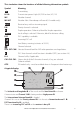
This simulation shows the locations of all the following information symbols: Symbol Meaning Transmitting. TX HI LO Transmission power. High (HI) 25 W or Low (LO) 1 W. WX Weather channel. WX ALT Weather Alert. Alarm beeps will sound (US models only). BUSY Receiver busy with an incoming signal. PRI Priority channel is selected. D Duplex operation. Otherwise, blank for Simplex operation. LOCAL Local calling is selected. Otherwise, blank for distance calling. DSC DSC capability is available.
1-6 Basic Operation and Key Functions All possible keys and their functions are listed here. Note that some of the keys may not be available depending on your Simrad VHF radio model. 5 Key handset mic RS12 base station radio Key: Function: VOL/PWR Volume and Power Turn clockwise to power on. Continue to turn until a comfortable volume is reached. VOL/PWR will also adjust the settings of an external speaker, if connected.
ENT Enter (ENT) Use ENT when navigating menus, to confirm entries and edits. ACCEPT Received DSC Call mode: Press to change immediately to the requested channel. OPT Received Individual Call mode: Press to view any incoming individual call reply options. Send DISTRESS Call mode: Press to view and select any available options. ACK ESC Receive Individual Call, LL Request, DSC Test Call, or Distress relay (US only) mode: Press to acknowledge an incoming call when an ACK is requested.
PAUSE DISTRESS CALL mode only: Pause the automated distress alert resend countdown timer. SCAN Scan Press to scan between your current channel and the priority channel in DUAL or TRI WATCH mode. The weather channel is also scanned if the USA channel bank is selected and the weather alert mode (ALT) is ON. Hold down SCAN to enter ALL SCAN mode where the priority channel is checked every 1.5 seconds. When a signal is received, scanning stops at that channel and BUSY appears on the screen.
H/L Transmission Power (Located on the handset mic). High (HI) 25 W or Low (LO) 1 W. Press to toggle between high or low transmission power for the entire channel bank. The HI or LO selection is shown on the LCD. Some channels allow only low power transmissions. Error beeps will sound if the power transmission setting is incorrect. Some channels allow only low power transmissions initially, but can be changed to high power by holding down H/L and PTT at the same time.
Section 2 - The Radio Menu (MENU) 2-1 Radio Menu Options (Menu) The following options are available through MENU key: BUDDY LIST Maintain your buddy list. See Section 2-2. LOCAL/DIST Set radio sensitivity. See Section 2-3. BACKLIGHT Set backlight level. See Section 2-4.
2-2 Maintain Your Buddy List (BUDDY LIST) MENU SELECT ►BUDDY LIST LOCAL/DIST BACKLIGHT ▼ Use the Buddy List to store the names and associated MMSI’s of 20 favourite people. Names are stored in the order of entry, with the most recent entry shown first. The following sections show how to add, edit, and delete entries on your BUDDY LIST. Section 5 explains how to call a buddy.
2-2-3 Delete an Entry BUDDY LIST ►MANUAL NEW ALEX TOM TOM EDIT ►DELETE BUDDY LIST MANUAL NEW ALEX ►TOM DELETE BUDDY TOM ►YES NO 1. Select BUDDY LIST. Press ENT to display the list of entries. 2. Scroll down (if required) to the entry you want to delete and press ENT. 3. Select DELETE then select YES. 4. The entry is deleted immediately and the buddy list is displayed again.
2-4-1 Set the Backlighting Level BACKLIGHT ▀ ▀ ▀ ▀ LO HI PRESS ENT 1. Select BACKLIGHT. 2. Select a comfortable backlight level using + or - to change the setting. 3. Press ENT to enable the setting and return to the menu. Note: The DISTRESS key backlighting cannot be switched off. 2.4.2 Set the Contrast Level CONTRAST ▀ ▀ ▀ ▀ LO HI PRESS ENT 1. Select CONTRAST. 2. Select a comfortable contrast level using + or - to change the setting. 3. Press ENT to enable the setting and return to the menu.
2-5-2 Local Time (TIME OFFSET) The local time can be set by entering the time offset between UTC and local time as follows. GPS/DATA MANUAL ►SETTING SETTING ►TIME OFFSET TIME FORMAT TIME DISPL▼ TIME OFFSET ►+01:30 02:30PM LOC 1. Select GPS/DATA, then SETTING. 2. Select TIME OFFSET to enter the difference between UTC and local time. 15 minute increments can be used with a maximum offset of ±13 hours. In this example, a difference of +1.
1. Select GPS/DATA, then SETTING. 2. Select TIME FORMAT. 3. Select 12 Hr or 24 Hr as desired. In this example, 12 hour format has been selected and the LCD shows the AM or PM suffix. 2-5-4 Time Display Options (TIME DISPLAY) If you have entered the time manually, as described in the previous sections, the time is always shown on the screen with the prefix M.
2-5-7 GPS Alert Options (ALERT) The GPS alert is usually set to ON (on) so that if the GPS navigation receiver is disconnected, the alarm sounds. SETTING LL DISPLY ▲ COG/SOG ►GPS ALERT GPS ALERT ►ON OFF 1. Select GPS/DATA, then SETTING. 2. Select GPS ALERT. 3. Select ON (on) or OFF (off ) as desired. 2-6 GPS Simulator (SIMULATOR) The GPS Simulator is set to OFF whenever the radio is switched ON, or whenever real GPS data is available through the COM port. However, if you want to test it, turn it on.
Section 3 - Radio Setup Menu (RADIO SETUP) 3-1 Radio Setup Menu (RADIO SETUP) The following options are available through the MENU key: Channel band. UIC * See Section 3-2. CH NAME Edit or delete channel names. See Section 3-3. RING VOLUME KEY BEEP Set the volume level of the incoming call notification beeps. See section 3-4. Set the volume level of the beeps. See section 3-4. INT SPEAKER Switch ON/OFF (on/off ) the radio’s internal speakers. See section 3-5.
3-3 Channel Names (CH NAME) The channel charts are listed in Appendix C with their default name tags. CH NAME gives you the option to edit or delete the channel name tags displayed on the screen. RADIO SETUP ►CH NAME RING VOLUME KEY BEEP ▼ EDIT CH NAME TELEPHONE CH NAME TELEPHONE 01 TELEPHONE ►EDIT DELETE EDIT CH NAME PHONE1 ►YES NO 1. Select RADIO SETUP, then CH NAME. 2.
1. RADIO SETUP RING VOLUM▲ KEY BEEP ►INT SPEAKE▼ INT SPEAKER ►ON OFF 2. Select RADIO SETUP, then INT SPEAKER. Select ON (on) or OFF (off ) then press ENT to enable the setting and return to the menu. 3-6 Set the Priority Channel (WATCH MODE) For EU models, watch mode is similar to a dual watch, scanning between the priority channel CH16 and the working channel.
3-9 Select the GPS Source (GPS SOURCE) This radio can use either NMEA 0183 or NMEA 2000 protocol to receive GPS data from a compatible GPS unit. Note: NMEA 2000 SOURCE options will appear - up to 4 sources showing the actual source name - only if connected to an NMEA 2000 network. 1. Select RADIO SETUP, then GPS RADIO SETUP GPS SOURCE SOURCE. INT SPEAKE▲ NMEA 0183 2. Select the desired NMEA source COM PORT ►NSS then press ENT.
Section 4 - DSC Setup Menu (DSC SETUP) WARNING A valid USER MMSI must be entered into this radio before these DSC functions can be used. See below for instructions on how to enter your USER MMSI (USER MMSI). 4-1 DSC Setup - Menu Options The following options are available through the MENU key: Enter or view your user MMSI. See section 4-2. USER MMSI (If you do not have a user MMSI, see Appendix D.) Enter or change the name and/or details of a group. GROUP SETUP See section 4-3.
1. Select DSC SETUP, then USER MMSI. 2. If this is the first time that you are entering your user MMSI, a dashed line appears. Enter your user MMSI along the dashed line using the +/- keys as described in Section 1-4. Press ENT to confirm each correct entry and to move to the next digit. If you make an error, press - until < appears, then press ENT to backup and correct the entry. 3. Press ENT to store your user MMSI. 4.
4-3-2 Edit Group Name Details GROUP SETUP MANUAL NEW ►FISHER1 FRIENDS1 FISHER1 ►EDIT DELETE EDIT NAME FISHER1 EDIT MMSI 012345678 FISHER2 012345678 ►STORE CANCEL 1. Select DSC SETUP, then GROUP SETUP. The existing group names are displayed. Press + or - to scroll to the incorrect entry then press ENT. 2. Press ENT to edit. The group name details are displayed, with the cursor at the first character of the name. 3.
4-5 ATIS MMSI & ATIS Functionality EU models ONLY ATIS is only available in certain EU models. You must enter your ATIS MMSI to access ATIS functionality. ATIS must be used if you are navigating inland waterways within Europe. An ATIS MMSI is different to your DSC MMSI. ATIS sends a digital message each time that you release the PTT key. Inland waterways rules require 1 W Tx power on Channels 06, 08, 10, 11, 12, 13, 14, 15, 17, 71, 72, 74 and 77.
4-5-3 Enable ATIS Functionality (ATIS FUNC) ATIS functionality can only be activated if an ATIS MMSI has been entered. See 4-5-1. DSC SETUP INDIV REPL▲ ATIS MMSI ►ATIS FUNC ▼ 1. ATIS FUNC ►ON OFF DSC IS ON Select DSC SETUP, then ATIS FUNC. ATIS Note: It is not possible to have both ATIS ON (on) and DSC ON (on) simultaneously. If you want to activate ATIS, you must first switch DSC off. A note on the LCD will remind you if DSC is already ON.
DSC SETUP INDIV REPL▲ DSC FUNC ►LL REPLY ▼ LL REPLY MANUAL ►AUTO OFF 1. Select DSC SETUP, then LL REPLY. 2. Select your response and press ENT to confirm and return to the menu. 4-8 Automatic Channel switching (AUTO SWITCH) When a DSC call is received, it may include a request to change to a specific channel for subsequent communications.
4-9 DSC Test Reply (TEST REPLY) You can respond to incoming DSC TEST calls with an automatic response or with a manual response. MANUAL manual responce is required, press ENT to confirm or press ESC to cancel. AUTO automatically replies after a 10 second delay with an ACK to any incoming DSC TEST call.
Section 5 - Sending and Receiving DSC Calls WARNING A valid USER MMSI must be entered into this radio before these DSC functions can be used. See 4-2 Enter Your USER MMSI (USER MMSI). 5-1 What is DSC? DSC (Digital Selective Calling) is a semi-automated method of establishing VHF, MF, and HF radio calls. It has been designated as an international standard by the IMO (International Maritime Organization) and is part of the GMDSS (Global Maritime Distress and Safety System).
DSC CALL INDIVIDUAL ►LAST CALL GROUP ▼ Note that only three DSC call types can be shown at any one time on the screen. Press + or - to scroll up and down the DSC call types until the cursor is positioned at the desired option. Then press ENT. The DSC call types are: 5-2-1 Make a Routine Call (INDIVIDUAL) You can call any other person that has another DSC equipped radio.
5-2-2 Retrying a Routine Call 123456789 SEND AGAIN? ►YES NO 1. If there is no reply to your call after 30 seconds (UNABLE TO ACKNOWLEDGE) the radio asks if you want to retry the call (SEND AGAIN?). 2. Select YES and press ENT to retry the call. The radio will repeat this cycle twice. If the call still cannot be placed, the radio returns to normal operation.
1. Press CALL to enter DSC mode. then select LAST CALL. Press ENT to display the contact details of the most recent incoming call. 2. Press ENT to recall the caller. Select the working channel and press ENT. See details about the working channel in section 5-2-1, paragraph 3 above. 3. The radio summarizes the call details and asks for confirmation to send the call (SEND?). Press ENT to send the call, and continue as explained in Section 5-2-1.
DSC CALL GROUP ▲ ALL SHIPS ►CALL LOG ▼ BOBBY D INDIVIDUAL ROUTINE ►SEND? 01 BOBBY D INDIVIDUAL ROUTINE 10:45 UTC BOBBY D ►CALL BACK DELETE BOBBY D INDIVIDUAL ROUTINE ►INTER-SHIP 1. Press CALL to enter DSC mode, then select CALL LOG. The radio displays the contact details for the most recent incoming call as the first entry (01). 2. Press ENT to advance to next screen. 3. Again press ENT to confirm the call back, then set the working channel.
5-2-9 Call using the Sent Call Log (SENT CALL) The Call Log contains the contact details for the 20 most recent sent calls, so that you review details of the call. DSC CALL CALL LOG ▲ DISTR LOG ►SENT CALL ▼ BOBBY D INDIVIDUAL ROUTINE ►SEND? 3. 01 BOBBY D ►INDIVIDUAL ROUTINE 10:45 UTC BOBBY D ►CALL BACK DELETE BOBBY D INDIVIDUAL ROUTINE ►INTER-SHIP 1. Press CALL to enter DSC mode, then select SENT LOG. Scroll down to the desired sent call details. 2.
5-2-11 Make a DSC test call (DSC TEST) You can test your radio’s DSC operation by sending a DSC TEST CALL to a Buddy or other station equipped with a DSC radio. Note: You should not use a routine DSC call to test your radio and you should minimize the use of the safety channel for test purposes. 5-2-11-1 Send a DSC TEST call 1. Select DSC CALL then DSC TEST. 2. Select the buddy you want to call from your buddy list, or Select MANUAL NEW then enter the MMSI of the individual you want to call. 3.
TEST CALL FROM 123456789 ▼ 00:01 Note: These additional information screens are available by pressing the + and - keys. 4. CALL FROM 123456789 AUTO ACK ▲▼ 00:02 AUTO ACK IN 10S 10:12 UTC ▲▼ 00:04 123456789 AUTO ACK IN 10S ▲▼ 00:03 IN 10S 10:12 UTC ENT–> ACK ▲▼ 00:05 10:12 UTC ENT–> ACK KEY->SILENCE ▲▼ 00:06 If TEST REPLY is set to MANUAL, a manual responce is required, press ACK (ENT) to confirm or press QUIT (ESC) to cancel.
5-3-1 Receiving an All Ships Call (ALL SHIPS) 1. When you receive notification of an ALL SHIP call, press SILENCE (+ or - CH SELECT) to silence the alarm. The priority level and the user MMSI are displayed on the screen. If the radio recognises the user MMSI as one of your buddies, the buddy’s name is displayed in place of the user MMSI. 2. Press ACCEPT (ENT) to switch to the designated channel immediately or press QUIT (ESC) to return to the current working channel.
INDIVIDUAL SAFETY FROM TOM ▼ 00:12 Note: These additional information screens are available by pressing the + and - keys. 2. SAFETY FROM TOM AUTO SW OFF ▲▼ 00:15 AUTO SW OFF CH67 REQUEST 10:12 UTC ▲▼ 00:20 TOM AUTO SW OFF CH67 REQUEST ▲▼ 00:18 CH67 REQUEST 10:12 UTC ENT–> OPTION ▲▼ 00:23 10:12 UTC ENT–> OPTION KEY->SILENCE ▲▼ 00:25 Press OPT (ENT) for options on how you want to respond to the call.
However, If AUTO SWITCH =OFF, then AUTO SW OFF will be displayed and manual channel change is required: GP 012345678 CALL FROM TOM ▼ 00:12 Note: These additional information screens are available by pressing the + and - keys. 3. CALL FROM TOM AUTO SW OFF ▲▼ 00:22 AUTO SW OFF CH13 REQUEST 10:12 UTC ▲▼ 00:28 TOM AUTO SW OFF CH13 REQUEST ▲▼ 00:25 CH13 REQUEST 10:12 UTC ENT–> ACCEPT ▲▼ 00:32 10:12 UTC ENT–> ACCEPT KEY->SILENCE ▲▼ 00:35 The call data is stored in the Call Log (see Section 5-2-7).
Section 6 - Distress Calls WARNING A valid USER MMSI must be entered into this radio before these DSC functions can be used. See section 4-2 Enter Your USER MMSI (USER MMSI). 6-1 Sending a Distress Call 1. Open the red cover labelled DISTRESS to expose the red Distress key. 2. TO SEND AN IMMEDIATE DISTRESS CALL (Undesignated): HOLD DOWN the DISTRESS key for about 3 seconds, until you see the distress call sending message (DISTRESS CALL SENDING) on the screen.
6. After the Distress Call is sent, the radio waits for an acknowledgment. 7. The Distress Call is automatically re-sent every 3.5 to 4.5 minutes until a distress acknowledgement is received or: • Press RESEND (CALL) to immediately resend the Distress Call • Press PAUSE (3CH) to pause the automatic Distress Call resend timer • Press DISTR.
6-2 Receiving a Distress Call (DISTRESS!) 1. An alert sounds when a distress call (DISTRESS!) is received. Press SILENCE (+ or - CH SELECT) to silence the alarm. You do not need to send an acknowledgement. DISTRESS FLOODING 123456789 ▼ 00:01 FLOODING 123456789 82’50.178N ▲▼ 00:02 123456789 82’50.178N 024’45.342W ▲▼ 00:03 82’50.178N 024’45.342W 10:12 UTC ▲▼ 00:04 024’45.
For a Distress Acknowledgement (DISTRESS ACK) sent from the Search and Rescue (SAR) authorities of your country, your radio automatically cancels Distress Mode transmissions and CH16 appears. Press PTT to establish voice contact with the Search and Rescue (SAR) authority. The Search and Rescue (SAR) authorities of your country are the only instance allowed to send a Distress Acknowledgement (DISTRESS ACK).
Section 7 - Installation This Simrad radio is designed to generate a digital maritime distress call to facilitate search and rescue. To be effective as a safety device, this radio must be used only within the geographic range of a shore-based VHF marine Channel 70 distress and safety watch system. The geographic range may vary but under normal conditions is approximately 20 nautical miles. Installation Options There are two ways to install the radio.
Checklist The following items should be supplied in the box. Check before starting the installation and contact your dealer if an item is missing. Note: An antenna is not provided. Consult your Simrad dealer for advice if necessary. 11. Four nuts for the mounting gimbal 12. Two self-tapping screws for the microphone bulkhead mount 13. Two flat screws for the microphone bulkhead mount 1. Mounting gimbal for the VHF radio 14. Two spring washers for the microphone bulkhead mount 2.
Gimbal Installation 1. Hold the mounting gimbal at the chosen location and use a soft pencil to mark the screw hole positions onto the mounting surface. 2. If you can’t reach behind the mounting surface to attach the nuts, use the self-tapping screws instead of the flat screws shown in the picture. If you’re drilling into fibreglass, use a drill bit smaller than 3/16” (5mm) to drill the pilot holes. Otherwise, drill the four screw holes where marked, using a 3/16” (5 mm) drill bit.
radio with the central hole in each mounting bracket. 5. Use the two short M5x10 screws to screw the mounting brackets to the sides of the radio. 6. Slide each M5x32 screw through the screw hole in the mounting bracket, then attach the lock nut and the stopper. If your bulkhead exceeds 13 mm, the stopper nut can be discarded if necessary. 7. Tighten the M5x32 screws until the radio is held against the rear of the bulkhead. 8. Tighten up the lock nuts to secure the installation.
Fix the DSC label CAUTION A DSC warning label is supplied with US versions of this radio. To comply with FCC regulations, this warning label must be affixed in a location that is clearly visible from the operating controls of this radio. Make sure that the chosen location is clean and dry before applying this label. Connect the Radio Cables The connectors are on the rear of the base unit, as follows: GPS/COM connector.
Wiring for GPS/COM connector 2 Orange 8 Grey 4 Green 5 Yellow 1 Bare wire 3 White 6 Black 7 Blue Pin 1 2 3 4 5 6 7 8 Wire Red Orange White Green Yellow Black Blue Grey Function (Not used) OUT (+) Program/clone IN (-) IN (+) OUT (-) (To No connection (Not used) No connection (Not used) Wiring for NMEA 2000 connector 52 Notes No connection Pin 1 2 Wire Green Red Function Can-D, Drain wire, Shield Can-S, Power, +12 V DC 3 4 5 Black White Blue Can-C, Ground Can-H, Data HIGH Can-L, Data
Set Up the Radio CAUTION You can not make any DSC transmissions until you have obtained a user MMSI and entered it into your radio. You must obtain a user MMSI (Marine Mobile Service Identity) and enter it into your radio before you can use the DSC functions. The user MMSI is a unique nine digit number, similar to a personal telephone number. It is used on marine transceivers that are capable of using DSC (Digital Select Calling).
The Completed Installation SIMRAD PUS H STBY AUTO TO EN TER MARK MENU GOTO PAGES IN MOB OUT MOB External speaker NSS 7 GPS product GPS / COM NMEA 0183 connection cable VHF antenna Antenna cable NMEA 2000 connector Fuse on Red power cable External speaker cable Black power cable RS12 base unit with handset mic 12 V dc Battery CAUTION Under extreme operating conditions, the temperature of the rear heatsink on this radio may exceed normal surface temperatures.
Appendix A - Technical Specifications SIMRAD RS12 GENERAL Power supply: 12 V DC battery system Low battery alert: 10.6 V DC +/- 5% Current drain - Transmit Receive 5 A at 25 W Tx / 1.5 A at 1 W Tx (@ 12 V DC) Less than 250 mA in standby Temperature range: -20ºC to +55ºC (-4ºF to 131ºF) Usable channels: International, USA, Canada, Weather (country specific) Mode: 16K0G3E (FM) / 16K0G2B (DSC) DSC mode: Class D (Global) with dual receiver (individual CH70) Standards: ITU-R M.
FEATURES Flush mount kit Yes Dust Cover Yes Local/Distant control: Yes Position polling: Yes Group call: Yes Call logs: Yes - 20 individual and 10 distress Channel naming: Yes Tri watch: Yes Favourite channel scan: Yes All scan: Yes User programmable MMSI: Yes MMSI and NAME directory: Yes - 20 numbers & group TRANSMITTER Frequency: 156.025 - 157.
Appendix B - Troubleshooting 1. The transceiver will not power up. A fuse may have blown OR there is no voltage getting to the transceiver. a. Check the power cable for cuts, breaks, or squashed sections. b. After checking the wiring, replace the 7 Amp fuse (1 spare fuse is supplied). c. Check the battery voltage. This must be greater than 10.5 V. 2. The transceiver blows the fuse when the power is switched on. The power wires may have been reversed. a.
Appendix C - US & ROW VHF Marine Channel Charts The following channel charts are provided for reference only and may not be correct for all regions. It is the operators responsibility to ensure correct channels and frequencies are used for local regulations. C-1 International Channel Chart CH TX (MHz) RX (MHz) MODE TRAFFIC TYPE SHIP TO SHIP SHIP TO SHORE NAME TAG 01 156.050 160.650 D Public Correspondence No Yes TELEPHONE 02 156.100 160.
62 156.125 160.725 D Port Operations No Yes 63 156.175 160.775 D Port Operations No Yes PORT OPS 64 156.225 160.825 D Public Correspondence No Yes TELEPHONE 65 156.275 160.875 D Port Operations No Yes PORT OPS 66 156.325 160.925 D Port Operations No Yes PORT OPS 67 156.375 156.375 S Commercial, bridge-to-bridge Yes No BRIDGE COM 68 156.425 156.425 S Inter-ship Yes No SHIP-SHIP 69 156.475 156.475 S Port Operations Yes Yes PORT OPS 70 156.
C-2 USA Channel Chart CH TX (MHz) RX (MHz) MODE TRAFFIC TYPE SHIP TO SHIP TO SHIP SHORE NAME TAG 01A 156.050 156.050 S Port Operations, Selected VTS Areas Yes Yes PORT OPS/VTS 03A 156.150 156.150 S US Government, Coast Guard Yes Yes UNAUTHORIZED 05A 156.250 156.250 S Port Operations, Selected VTS Areas Yes Yes PORT OPS/VTS 06 156.300 156.300 S Inter-ship Safety Yes No SAFETY 07A 156.350 156.350 S Commercial Yes Yes COMMERCIAL 08 156.400 156.
68 156.425 156.425 S Boat Operations, Recreational Yes No SHIP - SHIP 69 156.475 156.475 S Boat Operations, Recreational Yes Yes PLEASURE 70 156.525 156.525 Digital Selective Calling - DSC ------ ------ DSC 71 156.575 156.575 S Boat Operations, Recreational Yes Yes PLEASURE 72 156.625 156.625 S Boat Operations, Recreational Yes No SHIP - SHIP 73 156.675 156.675 S Port Operations Yes Yes PORT OPS 74 156.725 156.
C-3 CANADA Channel Chart CH TX (MHz) RX (MHz) MODE TRAFFIC TYPE SHIP TO SHIP TO SHIP SHORE NAME TAG 01 156.050 160.650 D Public Correspondence No Yes TELEPHONE 02 156.100 160.700 D Public Correspondence No Yes TELEPHONE 03 156.150 160.750 D Public Correspondence No Yes TELEPHONE 04A 156.200 156.200 S Canadian Coast Guard, SAR Yes Yes CANADIAN CG 05A 156.250 156.250 S Port Operations, VTS in Selected Areas Yes Yes PORT OPS/VTS 06 156.300 156.
62A 156.125 156.125 S Canadian Coast Guard Yes Yes CANADIAN CG 64 156.225 160.825 D Public Correspondence, Duplex No Yes TELEPHONE 64A 156.225 156.225 S U.S. Government, Canadian Commercial Yes Fishing Yes UNAUTHORIZED 65A 156.275 156.275 S Port Operations Yes Yes PORT OPS 66A 156.325 156.325 S Port Operations Yes Yes PORT OPS 67 156.375 156.375 S Commercial, SAR Yes No COMMERCIAL 68 156.425 156.
5 . The letter “A” illuminated by the channel number indicates the Canada channel is simplex. This same channel is always duplex when selecting International. There is no “A” reference for International channels. The letter “B” is only used for some Canadian “Receive only” channels. 6 . Channel 70 is designated for use exclusively for Digital Selective Calling (DSC), such as Distress, Safety, and Ship Calls. No voice communication is allowed on CH70.
Appendix D - EU VHF Marine Channel Charts The following channel charts are provided for reference only and may not be correct for all regions. It is the operators responsibility to ensure correct channels and frequencies are used for local regulations. For specific channel information for your country, please refer to local authorities. D-1 EU International Channel Chart CH TX (MHz) RX (MHz) MODE TRAFFIC TYPE SHIP TO SHIP SHIP TO SHORE NAME TAG 01 156.050 160.
62 156.125 160.725 D Public Correspondence, Port Op No Yes PHONE-PORTOP 63 156.175 160.775 D Public Correspondence, Port Op No Yes PHONE-PORTOP 64 156.225 160.825 D Public Correspondence, Port Op No Yes PHONE-PORTOP 65 156.275 160.875 D Public Correspondence, Port Op No Yes PHONE-PORTOP 66 156.325 160.925 D Public Correspondence, Port Op No Yes PHONE-PORTOP 67 156.375 156.375 S Commercial, bridge-to-bridge Yes No SHIP-SHIP 68 156.425 156.
D-2 Inland Waterways Country Specific table - ATIS ON For specific channel information for your country, please refer to local authorities. CH SPECIFIC FOOTNOTES TRANSMITTING FREQUENCY (MHZ) SHIP SHIP-TO-SHIP SHIP-TO PORT NAUTICAL INFORMATION LAND 60 a) 156.025 160.625 x 01 a) 156.05 160.65 x 61 a) 156.075 160.675 x 02 a) 156.1 160.7 x 62 a) 156.125 160.725 x 03 a) 156.15 160.75 x 63 a) 156.175 160.775 x 04 a) 156.2 160.8 x 64 a) 156.225 160.
77 156.875 156.875 18 156.9 161.5 x 78 156.925 161.525 x 19 156.95 161.55 x 156.975 161.575 x 20 157 161.6 x 80 157.025 161.625 x 79 a) k) a) x 21 a) 157.05 161.65 x 81 a) 157.075 161.675 x 157.1 161.7 x 22 82 l) m) 157.125 161.725 x 23 m) 157.15 161.75 x 83 a) m) 157.175 161.775 x 24 m) 157.2 161.8 x 84 m) 157.225 161.825 x 25 m) 157.25 161.85 x 85 a) m) 157.275 161.875 x 26 m) 157.3 161.9 x 86 a) m) 157.325 161.
Explanation of specific footnotes in Country Specific table: a. In the countries mentioned under remark 2, it is strictly prohibited to use this channel. b. This channel is not allowed to be used between Rhine km 150 and km 350. c. In the Netherlands, this channel is used by for its on-scene communications during safety operations on the North Sea, IJsselmeer, Waddenzee, Ooster- and Westerschelde. d. This channel may also be used for piloting, mooring, tugging and for other nautical purposes. e.
D-3 Special Channels 2 CH SEND (MHz) RECEIVE (MHz) TRAFFIC TYPE SHIP TO SHIP SHIP TO SHORE NAME TAG 00 1 156.000 156.000 UK Coast Guard Users Yes Yes UK COAST GRD M1 157.425 157.850 UK Marina Channel M1 Yes Yes UK MARINA M2 161.425 161.425 UK Marina Channel M2 Yes Yes UK MARINA 31 157.550 162.150 INT’L, Duplex (Holland) No Yes NL MARINA 96H 162.425 162.425 INT’L (Belgium) No Yes BEL G MARINA L1 155.500 155.500 INT’L (Skandinavia) Yes No LEISURE 1 L2 155.
Notes: Simrad - RS12 Operation and Installation Instructions 71
1177 *988-10239-002*