RS90 Installation Manual ENGLISH simrad-yachting.
Preface Copyright © 2014 Navico. All rights reserved. Simrad® is a registered trademark of Navico No part of this manual may be copied, reproduced, republished, transmitted or distributed for any purpose, without prior written consent of Simrad Electronics. Any unauthorized commercial distribution of this manual is strictly prohibited. Simrad Electronics may find it necessary to change or end our policies, regulations, and special offers at any time. We reserve the right to do so without notice.
This manual represents the RS90 as at the time of printing. Navico Holding AS. and its subsidiaries, branches and affiliates reserve the right to make changes to specifications without notice. IMPORTANT 1. DSC functions will not operate on the RS90 until your MMSI has been entered. 2. The radio channels installed into this Simrad VHF radio may vary from country to country depending upon the model and government or national communications authority regulations. 3.
Simrad recommends that you check the requirements of your national radio communications authorities before operating DSC functions. RF emissions notice This equipment complies with FCC radiation exposure limits set forth for an uncontrolled environment. This device’s antenna must be installed in accordance with provided instructions; and it must be operated with minimum 96 cm spacing between the antennas and all person’s body (excluding extremities of hands, wrist and feet) during operation.
Industry Canada statement This device complies with Industry Canada license-exempt RSS standard(s). Operation is subject to the following two conditions: (1) this device may not cause interference, and (2) this device must accept any interference, including interference that may cause undesired operation of the devise. Le présent appareil est conforme aux CNR d’industrie Canada applicables aux appareils radio exempts de licence.
CE compliance statement This product complies with CE under R&TTE directive 1999/5/EC. The relevant Declaration of Conformity is available in the following website under the model’s documentation section: http://www.simrad-yachting.com Important safety information Read carefully before installation and use Warning: Indicates a potentially hazardous situation that could result in death or serious injury. Caution: Indicates a potentially hazardous situation that could result in minor or moderate injury.
Contents 8| 9 About this manual 10 System Overview 10 11 Introduction System overview diagram 12 Preparation 12 Checklist 14 Installation 14 14 16 17 18 19 21 21 26 26 27 Positioning Installing the transceiver Installing a wireless handset cradle Installing a wired handset cradle Installing a handset cable connector External speakers installation options Transceiver external connectors Transceiver internal connectors Setting up the radio NMEA 2000 Network NMEA 2000 Network Diagram 28 Append
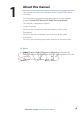
1 About this manual This manual describes the installation of the Simrad RS90 marine VHF radio. For instructions on operating the radio, please see the separate manual: Simrad RS90 Marine VHF Radio Operating Manual. This manual is organized as follows: • System Overview Describes the components and main features of the radio. • Preparation Describes the parts and tools you need to install the radio. • Installation Describes the mounting instructions and electrical connections.
2 System Overview Introduction The Simrad RS90 VHF radio is a comprehensive solution for marine VHF radio applications. The radio comprises: • RS90 VHF transceiver • One wired handset as standard, and optionally up to 3 more wired handsets.
System overview diagram 10 9 1 + 12 VDC 8 2 7 6 4 5 3 System Overview | RS90 Installation Manual | 11
3 Preparation Caution: Under extreme operating conditions, the temperature of the rear heat-sink on this radio may reach a surface temperature that is unsafe to touch. Caution is advised to prevent possible skin burns. ¼¼ Note: You must obtain a Maritime Mobile Service Identity (MMSI) for the vessel before you can use the Digital Selective Calling (DSC) function of this radio. Consult your local maritime authority or radio spectrum authority to obtain your MMSI.
Transceiver • RS90 transceiver unit • 2 m power supply cable • 8-pin terminal connector x4 • 2-pin terminal connector x2 • Spare 10 A fuse • Transceiver fasteners: • M3.5 mm x 23 mm self-tapping screw x4 • M3.5 x 28 mm machine screw x4 • M3.
4 Installation Positioning Transceiver Make sure that the position of the transceiver: • Is at least 1 m (39 inches) from the VHF antenna. • Allows easy connection to the 12 VDC electrical source, the antenna, and the NMEA 2000 connection. • Is at least 45 cm (18 inches) from any magnetic compass to avoid magnetic deviation of the compass during radio operation. • Provides suitable space for installing the wired handset cradle(s) nearby. (A 20 m extension cable is available as an optional extra.
211.2 mm (8.31”) 65.0 mm (2.56”) 92.4 mm (3.64”) 15.5 mm (0.61”) 195.7 mm (7.70”) 195.1 mm (7.
Installing a wireless handset cradle The wireless handset has a cradle that incorporates inductive charging for the rechargeable battery. 1. Choose a suitable location that provides sufficient room for the handset to fit securely in the charging cradle. 2. Hold the cradle at the chosen location and mark the positions of the fastening holes and the wire hole onto the mounting surface. 3. Drill the holes where marked. 4. Feed the wire through the wire hole. If mounting outside, seal the wire in the hole. 5.
Installing a wired handset cradle This is the same as installing a wireless handset cradle with the exception that no wiring is required. Fastenings • Top holes 2 x M3.5 x 28 mm machine screws, nuts and washers, or 2 x 3.5 mm self-tapping screws • Bottom hole 1 x M3 x 40 mm machine screw, nut and washers, or 1 x 3 mm x 40 mm self-tapping screw. 122.0 mm (4.80”) 191.5 mm (7.54”) 2 x 5.0 mm (0.20”) holes 202.5 mm (7.97”) 20.0 mm (0.79”) 69.0 mm (2.72”) 1 x 3.5 mm (0.
Installing a handset cable connector Each wired handset cable includes a connector assembly that must be installed in a bulkhead, dashboard or other suitable panel.
External speakers installation options Flush mount option 1. Fit the foam gasket to the rear of the speaker and remove the plastic trims that cover the screw holes. 2. Cut a 92 mm (3 5/8”) diameter hole in the mounting surface, allowing space for the speaker’s overall dimensions. 3. Temporarily fit the speaker and mark the four screw holes. 4. Drill holes of appropriate size for fasteners to be used. 5. Fit the speaker and secure with a small amount of sealant applied to the fasteners. 6.
External speaker - surface mount option 1. Position the surface mount box and mark the four screw holes through it. 2. Drill a hole in the mounting surface for the speaker wire and feed the wire through the hole. 3. Seal the cable in the hole in the mounting surface. 4. Lift the plastic trims that cover the screw heads. 5. Fix the speaker with fasteners through it and the box. 6. Replace the plastic trims.
Transceiver external connectors VHF antenna A suitable radio antenna (not supplied) must be mounted and connected with a PL295 connector before you can operate the radio. Consult your Simrad dealer for advice, if necessary. Always mount the VHF antenna as high as possible and at least 1 m (39 inches) from the transceiver. NMEA 2000 (N2K) connector The RS90 radio can be connected to an NMEA 2000 network using a cable (not supplied). For further information, see “NMEA 2000 Network” on page 26.
Transceiver internal connector numbering 22 | Installation | RS90 Installation Manual
Connector 1 - Fuse Install a 10 Amp MINI® blade fuse. Connector 2 - Power connection Label VCC GND Wire colour Red Black ¼¼ Notes: • Voltage: 12 VDC (10.8 VDC to 15.6 VDC) • Ground must be connected to the vessel’s common ground, which must be negative.
Connector 7 - External speakers Number 1 2 3 4 5 6 7 8 Label GND SPK1 GND SPK2 GND SPK3 GND SPK4 Wire colour Black Red Black Red Black Red Black Red You can connect a 4 W 8 Ω or an 8 W 4 Ω speaker to each pair of speaker terminals.
Connector 9 - AIS Data Output (NMEA 0183HS 38400 bps ) Number 1 Label RS422+ 2 3 RS422AIS_TX 4 5 6 7 8 GND AIS_RX GND - Description Output+ (RS-422 type) AIS RS422 data output only Output- (RS-422 type) Output+ (RS-232 type) Connect to PC or chart plotters Output- (RS-232 type) Not used Not used - Connector 10 - Loud hailer speaker Number 1 2 Label HAILER SPK+ HAILER SPK- Description Important: Do not short circuit these 2 connectors.
Setting up the radio ¼¼ Note: You must enter your User MMSI before the DSC functions of this radio will work. See the Setup section in the RS90 Operating Manual for full setup details. NMEA 2000 Network The radio can be connected to an NMEA 2000 network using an NMEA 2000 compliant cable (not supplied).
NMEA 2000 Network Diagram SIMRAD PU SH STBY AUTO 1 TO E NTE R MARK MENU GOTO PAGES IN MOB OUT MOB 2 NSS 7 + 12 VDC 5 3 120 120 4 T T 6 Installation | RS90 Installation Manual | 27
Appendix 1 - Accessories Part number 000-11226-001 000-11227-001 000-11228-001 000-11229-001 000-10791-001 000- 28 | Description HS90 handset and speaker kit RS90 transceiver HS90 handset External speaker HS35 wireless handset 20 m extension cable for handset Installation | RS90 Installation Manual
1177 *988-10497-001*