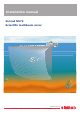
Installation manual Simrad MS70 Scientific multibeam sonar (CD016018B) www.simrad.
Simrad MS70 Installation manual This manual provides you with the basic information required to install the Simrad MS70. For more detailed information about the practical use of the product, refer to the Simrad MS70 Operator manual. This manual has been prepared for Generic delivery.
Revision status Simrad doc.no.: 331549 / Vessel: Generic / Current revision: B. Rev.A 04.03.2011 First version Rev.B 24.03.2011 Two chapters added. For details, see the record of changes in About this manual on page 9. Copyright ©2011 Kongsberg Maritime AS The information contained in this document remains the sole property of Kongsberg Maritime AS.
Installation manual Table of contents ABOUT THIS MANUAL ....................................................... 9 SIMRAD MS70................................................................. 11 Functional description ............................................................................................ 11 System description .................................................................................................13 System diagram ................................................................
Simrad MS70 Transducer installation procedure ..........................................................................31 Installation principles .................................................................................. 31 Preparations ............................................................................................... 32 Mounting the array ..................................................................................... 33 Cables....................................................
Installation manual About the Transceiver Unit ....................................................................................65 Transceiver Unit purpose............................................................................. 65 Transceiver Unit parts identification............................................................. 65 Mounting the TRXU racks .....................................................................................68 Mounting the Ethernet switch ............................
Simrad MS70 Transducer cable pairs................................................................................115 Element organisation..................................................................................116 Channel and element identification tables ....................................................117 Moxa CP134U-I Serial adapter setup...................................................................125 Serial line support ...............................................................
Installation manual Environmental requirements ................................................................................174 DRAWING FILE ............................................................. 175 Multibeam Operator Station (341305) .................................................................176 Transceiver Unit outline (281020) .......................................................................177 Power Supply Unit outline (311237).....................................................
Simrad MS70 8 331549/B
About this manual About this manual Purpose The purpose of this manual is to provide the information and basic drawings required for installation of the Simrad MS70. For more detailed information about the practical use of the product, refer to the Simrad MS70 Operator manual. About the technical descriptions and the target audience This manual describes the installation of the Simrad MS70. The manual is intended for technical personnel; qualified maintenance engineers and technicians.
Simrad MS70 Installation drawings Detailed vessel specific mechanical drawings for the installation must be provided by the customer, or any shipyard contracted to perform the installation. Kongsberg Maritime AS may, on special order, provide assistance to these drawings. Drawings must be approved by the appropriate vessel certification authority prior to installation of the system. Applicable outline dimension and productions drawings are provided in the Drawing file chapter.
Simrad MS70 Simrad MS70 Study this chapter to familiarize yourself with the Simrad MS70.
Simrad MS70 Figure 1 Operational principle The Simrad MS70 Scientific multibeam sonar transducer is designed to be mounted on a drop keel. From this position, it will look horizontally athwartship, and provide a matrix of beams. This configuration allows for characterization and volume estimation of a school of fish using a single transmission. Schools of fish can be tracked, followed and studied using multiple transmissions.
Simrad MS70 System description The Simrad MS70 is the world’s first quantitative multibeam sonar for fishery research applications The MS70 transducer array provides a matrix of acoustic beams. The array is normally mounted on a drop keel, which allows it to look horizontally. The MS70 allows you to perform characterization and volume estimation of a school of fish using a single transmission. Schools of fish can be tracked, followed and studied during multiple transmissions.
Simrad MS70 The 25 cables from the transducer (D) are connected to the three transceiver shelves (TRXU) in the transceiver (B). An Ethernet switch controlling two local area networks within the transceiver distribute the processing tasks between the six beamforming computers (TRC). The operator station is connected to these networks by means of an Ethernet cable (1).
Simrad MS70 The main components in the transceiver are: • 3 ea TRXU Transceiver subracks • 6 ea TRC Beamforming computers • 1 ea Ethernet switch • Cabinet fan unit Power Supply Unit The Simrad MS70 comprises three Power Supply Units. Each unit provides AC and DC power to one of the three transceiver racks in the transceiver. External analogue power supplies have been chosen to ensure minimum electric noise.
Simrad MS70 • One is used to power the Power Supply Units, and thus the Transceiver Unit. Uninterrupted power supply (UPS) units are not included in the standard MS70 delivery. Several commercial types are available. To choose the best UPS for the MS70 installation, consider environmental conditions, space available, the availability and duration of the batteries, and the power requirements of the MS70 units.
Simrad MS70 General supply conditions The following supply conditions are applicable to this Simrad MS70 delivery. Equipment responsibility The shipyard performing the installation and/or equipment dealer becomes fully responsible for the equipment upon receipt unless otherwise stated in the contract. The duration of responsibility includes: • The period of time the equipment is stored locally before installation. • During the entire installation process. • While commissioning the equipment.
Simrad MS70 General installation requirements The following installation requirements are applicable to this Kongsberg Maritime delivery. Approval by classification society The Simrad MS70 transducer installation must be approved by Det Norske Veritas (DNV) or another classification society. The shipowner and shipyard performing the installation are responsible for obtaining the installation approval.
Simrad MS70 Note The location of the transducer and/or protection blister must be noted on the vessel’s docking plan for future reference. Prior to dry docking, power down all hydroacoustic systems, and label each system accordingly to prevent accidental power on. Remove circuit breakers if necessary. Wiring All cables running between system cabinets located in different rooms and/or on different decks must be supported and protected along their entire lengths using conduits and/or cable trays.
Simrad MS70 USA • Address: 19210 33rd Ave W, Lynnwood, WA 98036, USA • Telephone: +1 425 712 1136 • Telefax: +1 425 712 1193 • E-mail address: simrad.usa@simrad.com • Website: http://www.simrad.
Installation planning Installation planning This chapter provides the marine engineers responsible for the installation the information necessary to plan the installation the Simrad MS70 according to Kongsberg Maritime’s requirements. Correct installation of the MS70 transducer is vital to the system’s performance. Several variables must be taken into consideration, the most important of which is the vessel’s construction.
Simrad MS70 Where to mount the transducer A single answer to the question where to locate the transducer cannot be given. It depends very much on the vessel’s construction, how the hull is shaped and how the water runs along the hull. There are however a number of important guide lines, and some of these are even conflicting. Mount the transducer deep Mount the transducer at a deep position on the hull. Consider the situations when the vessel is unloaded, and when it is pitching in heavy seas.
Installation planning For the same reason, it is very important that the hull area around the transducer face is as smooth and level as possible. Even traces of sealing compound, sharp edges, protruding bolts or bolt holes without filling compound will create noise. Avoid the boundary water layer Mount the transducer at the forward part of the hull to minimise the effects from the boundary water layer.
Simrad MS70 Avoid all propellers Mount the transducer far away from the propellers. The propulsion propeller is the dominant noise source on most fishing vessels, research vessels, merchant vessels and pleasure crafts. The noise is transmitted through the sea water. For this reason, the transducer should be placed far away from the propeller, which means on the fore part of the hull. Positions outside the direct line of sight from the propeller are favourable.
Installation planning If the vessel hull has a bulbous bow, this may well be a good transducer location, but also here must be taken into consideration the flow pattern of the aerated water. Often the foremost part of the bulb is preferable. Figure 6 Recommended location of the transducer on a bulbous hull A Thruster B Transducer location Sonar room requirements The “sonar room” is the compartment in which the Transceiver Unit and the Power Supply Units are installed.
Simrad MS70 Insulation Bulkheads must be insulated and provided with an interior wall to the deck. The insulation should be the minimum equivalent of 50 mm of rock-wool. In addition, piping passing through the space prone to condensation must be insulated. Ventilation The sonar room must be connected to the vessel’s ventilation system. If this is not possible, two 3” vents must be provided from the sonar room to the main deck.
Installation planning • Transducer cables The power cables from the three Power Supply Unit cabinets must be run in steel conduits. → Steel conduits for power cables on page 56 The majority of the cables are provided by Kongsberg Maritime, but certain cables (in particular the cables to the external sensors) must be provided by the installation shipyard.
Simrad MS70 Transducer installation The purpose of this chapter is to provide generic descriptions and illustrations allowing the reader to understand the basic principles for echo sounder transducer installation. This information must be regarded as general guidelines and recommendations only. The installation shipyard must design and manufacture installation hardware to fit each individual transducer and vessel.
Transducer installation Transducer description The Simrad MS70 transducer is a short cylindrical container with the transducer array located at the bottom. The transducer cables penetrate the top of the cylinder. Figure 7 The Simrad MS70 transducer The transducer is mounted with twelve -12- bolts with M12 thread. A mounting ring must be welded to the blister plate. A clamping ring is then inserted sideways towards the mounting ring.
Simrad MS70 Handling rules Note Do not expose the transducer to direct sunlight! Do not expose the transducer to excessive heat! Do not use high pressure water, sand blasting or metal tools to clean the transducer face! Do not use strong solvents to clean the transducer face! Related topics • Rules for transducer handling on page 44 How to lift the transducer out of its transport crate The Simrad MS70 transducer is shipped in a large wooden crate.
Transducer installation 2 Remove the transport beam across the top of the transducer body. 3 Mount the three 10 mm lifting eye bolts. 4 Lift the transducer straight up and out of the crate. Support the cables during the lift to keep the transducer body from tilting sideways. 5 Place the protective wooden plate under the transducer body to protect its face. Transducer installation procedure Observe the following procedures to install the Simrad MS70 transducer array.
Simrad MS70 Figure 9 Transducer installation principle A Mounting ring (welded to the retractable keel’s side wall) B Clamping ring C Side wall of retractable keel D Bolts (12 x 12M) E Transducer face (CD016003A) The transducer is provided with three sacrificial zinc anodes mounted to its top surface (lid). These anodes must be replaced when 1/3 of their bodies have been spent.
Transducer installation Figure 10 Mounting and clamping rings A D G C E F B (CD016004A) A Mounting ring (to be welded to the retractable keel) B Clamping ring C Guidance notch in the mounting ring. This notch must be pointing UP! D M6 guidance bolt on the mounting ring. E M6 guidance hole on the clamping ring, will ensure that the clamping ring fits correctly on the mounting ring. F Hole for one of the 12 mounting bolts. G Self-locking thread to accept the mounting bolt.
Simrad MS70 Cables Place the cables in the cable ducts, and pull them through the applicable seals to the sonar room. 2 Check and verify that cables are installed in such a way that they are protected from sharp edges, shock and vibration, as well as occasional work on the vessel.
Transducer installation Transducer cables and conduit 25 cables arranged in three groups are used to connect the MS70 transducer array to the 19” rack with the transceiver circuitry. A Steel conduit B Watertight seal C Allow the transducer cables to move freely up and down D Secure the cables here E Steel conduit Figure 11 Designing the cable conduit By default, each cable is 25 meters long. The cables are cut to fit each individual installation.
Simrad MS70 Transducer alignment The Simrad MS70 is a precision instrument for scientific use. In order to produce data that are both detailed and correct, it is necessary to calibrate the survey vessel more accurately than what may have been a standard practice earlier. The results, with all measurements taken in a common vessel coordinate system must be entered as MS70 operational parameters.
Transducer installation It is easiest to perform these measurements with the vessel in dry dock, the others may be done with the vessel berthed. It is however recommended to perform these when in dry dock During the sea trials (SAT), calibration surveys are required as described in the MS70 Reference Manual. Based on the calibration parameters determined from these surveys, proper values are entered into the MS70 as operational parameters.
Simrad MS70 Figure 12 Vessel coordinate system with the reference point on the water line A Downward (Z-axis) B Starboard (Y-azis) C D A B C -Z Forward (X-axis) Reference point (origo) -Y -X D +X +Y (CD017013D) +Z Reference points must be established on the vessel at selected positions. These are needed during measurements of the sensor positions. Visual markings at these positions should be prepared and noted on the vessel drawings with X, Y and Z coordinates in the vessel coordinate system.
Transducer installation Heading sensor The alignment of the motion sensor and the heading sensor must be adjusted so that they provide zero values for pitch, roll and heading with the vessel lying still with normal trim and a true North heading. It is recommended that this takes place in the dry dock. Alternatively, the offsets from zero must be determined. This is easiest to do with the vessel berthed. Follow the procedures in the applicable sensor manuals.
Simrad MS70 Figure 13 Typical location of sensors -Z 3 5 2 4 -X +X R 1 (CD017013B) +Z 1 Location of the transducer array 2 Motion sensor 3 GPS Antenna 4 Draft 5 Water line R is the reference point (origo) Transducer array 1 Measure the vertical location of the transducer array with an accuracy of ±2 cm. 2 Measure the horizontal location of the transducer array with an accuracy of ±5 cm. 3 Measure the heading of the transducer to an accuracy of ±0.1°.
Transducer installation Note If the Motion Sensor performs lever arm correction to give heave data valid for another location than where it is actually mounted, it is this location which must be measured. 3 Set up the forward axis on the motion sensor with the X-axis of the vessel’s coordinate system to an accuracy of ±0.1°.
Simrad MS70 Coordinate systems The heading of the transducer array is measured as the heading of the projection of a line through the face index marks into the horizontal plane of the vessel coordinate system. If the array is mounted in such a way that the X-axis is vertical, the heading angle must be measured as the heading of the Y-axis with 90° subtracted. See the definition below.
Transducer installation Heading sensor calibration It may not be possible to calibrate the heading sensor accurately enough through sea trials, so the calibration is normally done with the vessel berthed. On the quay the geographical coordinates of two points must be known or measured so that the heading of a line on the quay can be established to an accuracy of better than ±0.1°.
Simrad MS70 Transducer handling and maintenance You MUST observe the following rules for handling, cleaning, maintenance and painting.
Transducer installation Rules for transducer maintenance Once installed, the transducer is maintenance free. However, when the vessel is docked, it is highly recommended to clean the transducer face to remove marine growth. 1 Perform a thorough visual check of the transducer. 2 If necessary, clean the transducer • To clean the transducer, use normal synthetic soap and water. • To remove marine growth, use fine-grade sandpaper or emery paper.
Simrad MS70 International Marine Coatings Address: World-wide offices Website: www.international-marine.com. 1 Intersleek tie coat + 425 FCS • BXA386/BXA390/BXA391 Grey • HKA563/HKA570/HKA571 Yellow • Mix BXA386, BXA390 and BXA391 first, then apply. When dry, mix HKA563, HKA570 and HKA571, apply. 2 Intersmooth 360 Ecoloflex SPC 3 Micron Extra Hempel IFA Coatings Head office address: Hempel A/S, Lundtoftevej 150, Kgs. Lyngby, DK-2800 Copenhagen, Denmark Website: www.hempel.com.
Transceiver Unit installation Transceiver Unit installation This chapter explains how to install the Simrad MS70 Transceiver Unit. The Transceiver is normally positioned in a dedicated room in the vicinity of the transducer. The physical length of the cables limit the physical distance between the transducer and the transceiver.
Simrad MS70 Note The Transceiver Unit is shipped as a “wired rack”. This means that the 19” instrument rack is empty. The TRXU subracks, Ethernet switch and TRC computers are not mounted. However, all internal mounting material and wiring have been prepared to accept these units. The physical installation of the electronic units, the internal wiring and the setting-to-work procedures are done by personnel from Kongsberg Maritime AS.
Transceiver Unit installation Transceiver Unit preparations The instrument rack housing the Transceiver Unit is equipped with shock absorbers at the bottom of the cabinet and at the left hand side. This means that the cabinet is designed to be installed alongside a bulkhead. A U-shaped steel profiles, must provide minimum 10 cm height B Cable tray C Grounding Figure 14 Transceiver Unit positioning and grounding This procedure outlines the necessary tasks to prepare the transceiver for installation.
Simrad MS70 7 Check that the sonar room requirements are met. → Sonar room requirements on page 25 Transceiver Unit installation procedure This procedure explains how to install the Transceiver Unit. The Transceiver Unit is housed in a 19 inch commercial instrument rack. The chosen method for mounting the cabinet must be determined by the installation shipyard and the customer. The cabinet may be welded to the deck and bulkhead brackets, or mounted using suitable bolts.
Transceiver Unit installation Forward view Figure 15 Transceiver Unit, front view A Transceiver rack TRXU0 A (CD016006-019) Eight TRX32 boards are used. B Transceiver rack TRXU1 Eight TRX32 boards are used. C Transceiver rack TRXU2 Nine TRX32 boards are used. D Ethernet switch E TRC0–5 Beamforming computers TRC0 (top) is the master.
Simrad MS70 Rear view Figure 16 A B Transceiver Unit, rear view D C E A Power distributor PD2 B Power distributor PD1 C Power distributor PD1 D Rear side of Transceiver rack TRXU0 E Rear side of Transceiver rack TRXU1 F Rear side of Transceiver rack TRXU2 G Rear side of Ethernet switch H Rear side of TRC Beamforming computers I Circuit breakers (from left) CB0, CB1, CB2, CB3 F (CD016006-020) G H I 52 331549/B
Power Supply Unit installation Power Supply Unit installation This chapter explains how to do the physical installation of the Power Supply Units. The three units are installed in the sonar room within reasonable distance from the Transceiver Unit. The physical length of the power cables limit the physical distance between each Power Supply Unit and the Transceiver Unit.
Simrad MS70 About the Power Supply Unit The Simrad MS70 comprises three Power Supply Units. Each unit provides AC and DC power to one of the three transceiver racks in the transceiver. External analogue power supplies have been chosen to ensure minimum electric noise. In order to reduce the voltage drop in the power cables between each Power Supply Unit and the Transceiver Unit, these cables must be kept as short as possible. The cables must also be run in steel conduits to minimize electric noise.
Power Supply Unit installation 3 4 5 Provide ample space around the cabinet to allow for ventilation, inspection, maintenance and parts replacement. Make sure that the cabinet door can be fully dismounted for unobstructed access to its internal parts. • Minimum space requirement, front: 80 cm • Minimum space requirement, rear: 0 cm • Minimum space requirement, below: 0 cm (provided that the four feet are mounted) Check that the environmental requirements (temperature and humidity) for the sonar are met.
Simrad MS70 Steel conduits for power cables Note Due to the voltages and currents provided by the power supplies, steel conduits are imperative. Figure 18 Steel conduits principle The power cables from the three Power Supply Unit cabinets to the Transceiver Unit must be run in steel conduits.
Power Supply Unit installation Power Supply Unit installation procedure Depending on the installation method provided, two procedures are provided. Cabinets mounted side by side, or above each other 1 Observe the eight 8.5 mm mounting holes through the rear side of the two shock absorbers. 2 Arrange the necessary brackets on the bulkhead to fit the cabinets. 3 Prepare the brackets to accept the eight bolts. 4 If necessary, mount a temporary shelf under the cabinet to support its weight.
Simrad MS70 Figure 19 Power Supply Unit overview A Power supply +6 Vdc B Power supply +12 Vdc C Power supply +75 Vdc D Internet Power Switch E Fuse panel F Fan G Terminal board for all interface and power cables 58 331549/B
Multibeam Operator Station installation Multibeam Operator Station installation This chapter describes the installation of the Simrad MS70 Multibeam Operator Station.
Simrad MS70 Operator station installation requirements Figure 20 Multibeam Operator Station Installation of the MS70 Multibeam Operator Station units must be performed by qualified and trained personnel. Observe the following general guidelines for installation. • The safe navigation of the vessel. • The “Compass safe distance” for each individual unit. • Ergonomically correct operating and viewing heights. • Maximum allowable cable distances between the various units.
Multibeam Operator Station installation Installation procedure 1 Prepare the mounting location. → Multibeam Operator Station (341305) on page 176 2 Disassemble the base rails from the Processor Unit by removing the two front base rail screws. 3 Attach the base rails as shown in the figure. Note Note that the four rubber bushings must be mounted on top of the base rails. These are required to provide vibration and shock absorption between the base rails, and the rails mounted on the Processor Unit.
Simrad MS70 Operator station display monitor installation This section describes the installation of the MS70 Operator Station display. The make and model of the this display is determined by the customer. For this reason, the information provided here is only for guidance. For a detailed specific installation procedure, refer to the applicable documentation provided with the display. • The display must be located so that it is best protected from glare which reduces readability.
UPS installation UPS installation In order to ensure continuous operation of the Simrad MS70 independent of varying quality of the vessel’s mains supply, the use of uninterrupted power supplies (UPS) is important. A UPS system must be fitted to supply to the TRC computers in the Transceiver Unit. A UPS system is strongly recommended to power the Multibeam Operator Station and the Power Supply Units.
Simrad MS70 Transceiver Unit assembly When delivered, the MS70 Transceiver Unit is provided as a wired cabinet. This means that the cabinet is empty. None of the main modules are mounted. These are packed separately, and must thus be installed before the system can be set to work. This chapter provides the necessary procedures to install the transceiver modules and cables.
Transceiver Unit assembly About the Transceiver Unit This section provides a general description of the Transceiver Unit. Topics • Transceiver Unit purpose on page 65 • Transceiver Unit parts identification on page 65 Transceiver Unit purpose The transceiver performs the signal processing and digital beamforming of the transmitter and receiver channels. The MS70 Transceiver Unit is housed in a 19” instrument rack.
Simrad MS70 • TRC Beamforming computer • Cabinet fan unit Forward view Figure 22 Transceiver Unit, front view A Transceiver rack TRXU0 A (CD016006-019) Eight TRX32 boards are used. B Transceiver rack TRXU1 Eight TRX32 boards are used. C Transceiver rack TRXU2 Nine TRX32 boards are used. D Ethernet switch E TRC0–5 Beamforming computers TRC0 (top) is the master.
Transceiver Unit assembly Rear view Figure 23 A B Transceiver Unit, rear view D C E A Power distributor PD2 B Power distributor PD1 C Power distributor PD1 D Rear side of Transceiver rack TRXU0 E Rear side of Transceiver rack TRXU1 F Rear side of Transceiver rack TRXU2 G Rear side of Ethernet switch H Rear side of TRC Beamforming computers I Circuit breakers (from left) CB0, CB1, CB2, CB3 F (CD016006-020) G H I 331549/B 67
Simrad MS70 Mounting the TRXU racks This procedure explains how to install the three TRXU racks into the empty wired frame of the transceiver cabinet. Note Due to the physical weight of the racks, minimum two persons must be allocated to do this task. Standard workshop tools are required, as well as a torque wrench for Allen bolts. Important Each of the three TRXU racks are provided complete with all circuit boards and modules readily mounted.
Transceiver Unit assembly Figure 24 TRXU rack, front view Note that the physical appearance of the TRX32 circuit boards and the various labels on the rack may differ from this photo. A Ethernet cable, one is connected to each TRX32 circuit after the rack has been secured. B Eight bolts are used to secure the rack. Two of these bolts also holds the earth straps. C Earth straps D Air duct. This air duct is mounted in the empty transceiver cabinet during shipping.
Simrad MS70 Figure 25 TRXU racks 1 and 2, rear view with cables Note that the physical appearance of the various labels on the rack may differ from this photo. A Mounting rail for TRSU rack B Terminal board for power to TRXU No.1. C Terminal board for power to TRXU No.2. D Three Amphenol plugs connect the DC power cables to the rear side of the TRXU rack. E AC input F Synchronisation cables between the TRXU racks G One of the sockets for the transducer cables.
Transceiver Unit assembly Procedure 1 Remove the two earth straps on the right hand side of the transceiver cabinet. 2 Remove all the remaining 20 bolts that are temporarily mounted into their front holes. 3 On each of the six rails (three on each side), dismount the side rail that shall be mounted onto the TRXU racks. Figure 26 4 5 Remove the side rail (A) by unlocking it (B) Remove the rail bolts from the two side panels on each TRXU rack. Use the same bolts to mount the two side rails.
Simrad MS70 9 Connect the Ethernet cables to the corresponding sockets at the top of each TRX32 transceiver board. The Ethernet cables are pre-installed, and the length of each cable is adjusted to reach the individual TRX32 transceiver boards. 10 On the rear side of each TRXU rack, connect the four power plugs.
Transceiver Unit assembly Mounting the Ethernet switch This procedure explains how to install the Ethernet switch into the empty wired frame of the transceiver cabinet. Only standard workshop tools are required. The Ethernet switch rests on a set of angular shelves on each side of the rack. It is secured in position using four bolts. 1 Push the Ethernet switch in place on the shelves provided. 2 Secure the switch in position using the four bolts, two on each side.
Simrad MS70 Mounting the TRC Beamforming computers This procedure explains how to install the six TRC Beamforming computers into the empty wired frame of the transceiver cabinet. Note Due to the physical weight and the size of the computers, minimum two persons must be allocated to do this task. No tools are required. Important Each of the six TRC Beamforming computers are provided complete with all additional circuit boards and modules readily mounted.
Transceiver Unit assembly Figure 29 TRC Beamformer computer installation A The two bolts on each side of the computer cabinet fit into these slots in the rail B Press here (on each side) to push the computer into the rack. C Locking device to release the computer from the rails Procedure 1 Pull out the rails. 2 Lift the computer carefully, align the two bolts on each side so that they will fall into the corresponding slots on the rails.
Simrad MS70 Connecting the power cables from the Power Supply Units This procedure explains how to connect the power cables from the three Power Supply Units.
Transceiver Unit assembly 1 Connect each of the power cables to the three terminal boards in the Transceiver Unit. Figure 31 Power cables connected to the terminal board (example) • The top terminal board is used to accept the power cables from Power Supply Unit no.0. The power is then connected to TRXU no.0. • The bottom rear terminal board is used to accept the power cables from Power Supply Unit no.1. The power is then connected to TRXU no.1.
Simrad MS70 Connecting the transducer cables This procedure explains how to connect the transducer cables to the rear side of the TRXU racks. There are 25 transducer cables, and these are numbered 001 to 025.
Transceiver Unit assembly 1 For each transducer cable, locate the identification number. 2 Connect the plug to the correct socket on the correct TRXU, and tighten the bolts. Figure 33 Transducer cables connected to the rear side of the TRXU rack Observe the connection drawings provided. → Transducer cables on page 156 3 Collect the transducer cables in bundles, and secure these to the wired frame in the transceiver cabinet with wire wraps.
Simrad MS70 Cable layout and interconnections This chapter provides the cable plan and cable installation requirements for the Simrad MS70.
Cable layout and interconnections Read this first! Detailed information about cable specifications, termination and connectors are provided. All cables are provided by Simrad unless otherwise specified. In order to provide for maintenance and to allow for vibration, make sure that some slack is provided for all cables. A detailed drawing for each cable is provided.
Simrad MS70 Cable plans A detailed cable plan is provided. Due to the large number of cables, they are organized in groups, each with different leading characters.
Cable layout and interconnections Ethernet switch connectors The HP ProCurve 2910 Ethernet switch holds 48 front mounted connectors. The connectors are numbered 1 to 48 as shown in the illustration. Figure 34 HP ProCurve 2910 Ethernet switch connectors Note Although the Ethernet connectors on the switch appear identical, they are organized in two different logical groups. The Ethernet switch thus operates as a “dual” unit providing two separate networks.
Simrad MS70 System interconnection cables Figure 35 T1 230 Vac T2 230 Vac T3 230 Vac Cable plan, interconnection cables Power Supply Unit 0 U1 Display A1 Power Supply Unit 1 U2 Power Supply Unit 2 U3 Transceiver Unit D1 Operator Station 230 Vac W4 230 Vac W5 Trigger K1 GPS SV Gyro Spare A2 H1 H2 H3 H4 Ethernet W6 A3 Ethernet D2 Ethernet D3 MRU G1 230 Vac R1 Power cables provided by Simrad 001 to 025 230 Vac R2 Ethernet cables provided by Simrad 230 Vac R3 Power cables provided by sh
Cable layout and interconnections Ethernet cables; TRC computers Figure 36 Cable plan, Ethernet cables; TRC computers B2 19 B4 21 B6 23 B8 25 B10 B12 29 27 B3 B1 B5 35 33 36 39 38 B7 B9 41 40 B14 B13 B5 B7 37 B15 B9 B11 43 42 44 B16 B17 B11 TRC0 TRC1 TRC2 TRC3 TRC4 TRC5 1 1 1 1 1 1 2 2 2 2 2 2 3 3 3 3 3 3 4 4 4 4 4 B13 B14 B15 B16 B17 4 B3 B12 5 6 B4 B6 B8 B10 7 B2 8 9 10 B1 (CD016029-014) Related topics • [B] Ethernet cables to TRC
Simrad MS70 Ethernet cables; TRXU transceiver racks Figure 37 Cable plan, TRXU Ethernet Related topics • [C] Ethernet cables to TRXU transceiver racks on page 100 • RJ45 Ethernet, straight on page 147 86 331549/B
Cable layout and interconnections Ethernet cables; Operator Station and Power Supply Units Figure 38 Cable plan, Power and Multibeam Operator Station Ethernet Related topics • [A] Ethernet cables to Power Supply Units on page 97 • [D] Ethernet cables to external cabinets on page 101 • RJ45 Ethernet, straight on page 147 331549/B 87
Simrad MS70 Power cables; Transceiver Unit Figure 39 Cable plan, AC mains, Transceiver Unit TRXU0 TRC0 (Top) FAN UNIT TRC3 (Top) TRXU1 TRC1 TRC4 TRXU2 TRC2 TRC5 (Bottom) (Bottom) ETH.SW.
Cable layout and interconnections Power cables; Power Supply Units Figure 40 Cable plan, Power Supply Units and DC supply power Transceiver Unit TRXU0 U4A U4B U4C TRXU1 U4D U5A TB0 U5B U5C TRXU2 U5D U6A TB1 U6B U6C U6D TB2 + 6 Vdc + 6 Vdc + 12 Vdc + 75 Vdc + 230 V ac U1 POWER SUPPLY UNIT 0 T1 U2 POWER SUPPLY UNIT U3 1 T2 POWER SUPPLY UNIT 2 T3 Ship 's 230 V ac mains supply (CD016008-003) Related topics • [T] AC mains supply to Power Supply Units on page 110 • [U] Power cables
Simrad MS70 Transducer cables Figure 41 Cable plan, Transducer array Transceiver Unit TRXU0 Cables 001 - 008 TRXU1 TRXU2 Cables 009 - 016 Cables 017 - 025 (CD016008C) Related topics • Transducer cables overview on page 115 • Transducer cables on page 156 • Terminations to TRXU0 (Top subrack) on page 158 • Terminations to TRXU1 (Middle subrack) on page 159 • Terminations to TRXU2 (Bottom subrack) on page 160 • Transducer cables on page 115 90 331549/B
Cable layout and interconnections Interface cables; TRXU synchronization Figure 42 Cable plan, TRXU synchronization Related topics • [F] Internal TRXU synchronisation on page 102 • Transceiver Unit TRXU synchronization cable on page 144 331549/B 91
Simrad MS70 Interface cables; Motion Reference Unit Figure 43 Cable plan, Motion Reference Unit interface Transceiver Unit TRC0 TRC1 TRC2 TRC3 TRC4 TRC5 Serial G1 (CD016008D) Motion Reference Unit Related topics • [G] Motion Reference Unit interface on page 103 • Generic RS-232 Serial line on page 130 92 331549/B
Cable layout and interconnections Interface cables; GPS, sound velocity and gyro Figure 44 Cable plan, GPS, Sound velocity and Gyro interfaces (CD016008D) Operator Station Power supply AC Mains Alternative 1: USB adapter Computer providing USB interfaces USB x 1 Alternative 2: Cable adapter Computer with serial interface board RS-232 x 4 H4 Alternative 3: H3 Computer RS-232 x 4 providing sufficient interfaces H2 H1 Spare Course gyro Sound V elocity sensor Global Positioning System Relate
Simrad MS70 Interface cables; external trigger Figure 45 Cable plan, External trigger Operator Station Computer RS-232 K1 External trigger (CD016008D) Related topics • [K] External trigger on page 105 • RS-232 cable applied as external trigger (1:1) on page 132 94 331549/B
Cable layout and interconnections Multibeam Operator Station cables Figure 46 Cable plan, Multibeam Operator Station Display W11-15 Other interfaces W4 230 Vac W7-10 Serial lines W1 Display W6 Ship 's Ethernet Computer W5 230 Vac D1 Ethernet communication with Transceiver Unit (CD016008-005) W3 Keyboard W2 Mouse Related topics • [D] Ethernet cables to external cabinets on page 101 • [W] Operator Station cables on page 113 • Generic RS-232 Serial line on page 130 • Generic RS-422 Serial line on p
Simrad MS70 Detailed list of cables The list below specifies each cable used by the Simrad MS70. References are made to the detailed cable drawings with applicable specifications.
Cable layout and interconnections [A] Ethernet cables to Power Supply Units Cat.5 Ethernet cables are used, the default colour is grey. All are wired “straight“ (no crossovers). The length of the cables are defined by the physical distance between the Transceiver Unit and the Power Supply Units. All cables are provided by Kongsberg Maritime.
Simrad MS70 [B] Ethernet cables to TRC Beamforming computers Cat.6 Ethernet cables are used. Neither of the Ethernet cables are screened, and all are wired “straight“ (no crossovers). Even numbered cables are normally green, and connect to port “1” on all the TRC Beamforming computers. Odd numbered cables are normally red, and connect to port “2” on the TRC Beamforming computers. Additional Ethernet cables are connected to the TRC0 Beamforming computer. All cables are 2 meters long.
Cable layout and interconnections Table 3 Ethernet TRC Beamforming computers (cont’d.
Simrad MS70 [C] Ethernet cables to TRXU transceiver racks Cat.6 Ethernet cables are used. Neither of the Ethernet cables are screened, and all are wired “straight“ (no crossovers). By default, all cables are blue. Those connected to TRXU0 are 2 meters long, the others are 1.5 meters long. All cables are provided by Kongsberg Maritime.
Cable layout and interconnections [D] Ethernet cables to external cabinets D1 is a standard Cat 6 Ethernet cable used to connect the Ethernet Switch in the Transceiver Unit to the Multibeam Operator Station. The cable colour is grey. The cable is wired “straight“ (no crossovers). The length of the cable is defined by the physical distance between the Transceiver Unit and the Multibeam Operator Station. The cable must be provided by the installation shipyard.
Simrad MS70 [F] Internal TRXU synchronisation Two special cables are used to synchronise the transmission in the Transceiver Unit. The two cables are connected from the TRXU2 rack (bottom) to TRXU1, and from TRXU1 to TRXU2 (top). Both cables are provided by Kongsberg Maritime.
Cable layout and interconnections [G] Motion Reference Unit interface A single serial line cable is connected to the RS-232 port on the rear side of the TRC0 Beamforming computer. Figure 49 RS-232 connector on the rear side of the TRC0 Beamforming computer The cable must be provided by the installation shipyard.
Simrad MS70 [H] GPS, Sound Velocity and Gyro interface Commercial RS-232 serial line cables are used to connect these inputs to the Multibeam Operator Station computer. Several computers may not offer the required amount of serial lines. In order to provide the necessary serial interfaces, additional serial line adapters may be added to the computer. As an alternative, RS-232 to USB adapters can be used.
Cable layout and interconnections [K] External trigger Various trigger signals are required for the MS70. Some of these trigger signals are connected to or from external devices, while others are connected internally. The following trigger signals are in use: • External trigger: In order to allow for external triggering to or from other acoustic systems on the ship, a serial line on the Multibeam Operator Station computer is used. Whenever possible, a standard serial line interface should be used.
Simrad MS70 [P] Power cables to TRC Beamforming computers Standard commercial 230 Vac power cables are used on all TRC Beamforming computers. The AC power distribution inside the rack is provided by four circuit breakers at the bottom of the cabinet, and three distribution rails at the top. Figure 50 AC distribution rail The units are powered from the three distribution rails as specified in the table.
Cable layout and interconnections [Q] Power cables to TRXU transceiver racks When the Power Supply Units are used, all DC and AC voltages required by the TRXU racks are provided by these external supplies. Distributor 0 and Circuit Breaker 0 are then not in use. These devices are however installed for test purposes, and to provide power for potential future power modifications.
Simrad MS70 [R] Power cables to ship’s 230 Vac mains supply The power cables provided to supply the Transceiver Unit with 230 Vac mains are connected to the four circuit breakers in the bottom of the rack.
Cable layout and interconnections [S] Power cables from the four circuit breakers Circuit breakers 0, 1 and 2 feed the three power distributors at the top of the rack, and cables S1, S2 and S3 are fitted to these distributor devices. Cable S4 powers the main fan at the bottom of the rack.
Simrad MS70 [T] AC mains supply to Power Supply Units The three external Power Supply Units are powered by from a 230 Vac 16A mains outlet. The DC output is fed to the three TRXU transceiver subracks by means of three cable bundles. Table 10 AC mains to Power Supply Units Cable From To T1 Ship’s mains supply Power Supply Unit 0 T2 Ship’s mains supply Power Supply Unit 1 T3 Ship’s mains supply Power Supply Unit 2 All cables are provided by Kongsberg Maritime.
Cable layout and interconnections [U] Power cables from Power Supply Units to Transceiver Unit The DC power from the three Power Supply Units are connected to the Transceiver Unit using bundled cables. Each bundle holds the following cables: a 230 Vac to TRXU fans b +6 Vdc (one red and one blue cable) c +6 Vdc (one red and one blue cable) d +12 Vdc (one red and one blue cable) e +75 Vdc (one red and one blue cable) Observe the block diagram.
Simrad MS70 Related topics • Power cables; Power Supply Units on page 89 • Power Supply Units DC output wiring on page 138 • TRXU racks DC input wiring on page 139 • Power Connector Panel on page 140 • +6 and +12 Vdc to the TRXU backplane on page 141 • +75 Vdc to the TRXU backplane on page 142 112 331549/B
Cable layout and interconnections [W] Operator Station cables These cables are used on the Operator Station. • W1 / Display: This is a commercial display cable. It provides the connection between the computer and the colour monitor. The type of cable used will depend on the video format required by the display (VGA/SVGA/DVI). • W2 / Mouse: This is a commercial cable, and in most cases, it is fixed to the mouse. Ensure that the plug on the mouse cable is compatible with the computer (USB/PS2).
Simrad MS70 Table 12 Multibeam Operator Station (cont’d.
Cable layout and interconnections Transducer cables overview A total of 25 transducer cables are brought up from the transducer array. Each cable is terminated in a large connector, and each connector plugs into its dedicated socket on the rear side of the TRXU transceiver subracks. The transducer cables are identified with numbers 001 through 025 All transducer cables are provided by Kongsberg Maritime.
Simrad MS70 Element organisation Figure 52 Transducer element organisation 0 1 2 3 4 5 6 7 D E 8 9 10 11 12 13 14 15 16 17 18 19 20 21 22 23 24 25 26 27 28 29 30 31 B 011 TRX-02 C A 001 TRX-04 002 TRX-09 003 TRX-14 004 TRX-19 005 TRX-24 006 TRX-03 007 TRX-08 008 TRX-13 009 TRX-18 010 TRX-23 011 TRX-02 012 TRX-07 013 TRX-12 014 TRX-17 015 TRX-22 016 TRX-01 017 TRX-06 018 TRX-11 019 TRX-16 020 TRX-21 021 TRX-00 022 TRX-05 023 TRX-10 024 TRX-15 025 TRX-20 (CD016010A) The tra
Cable layout and interconnections Channel and element identification tables The tables below defines the relationship between the elements and the individual channels. They also define which cable that is used, and to which TRX32 circuit board the element is physically connected. Figure 53 19 Transducer channel organisation 39 779 799 18 17 16 15 14 13 12 11 10 9 8 7 6 5 4 3 2 1 21 0 20 40 740 760 780 (CD016010B) The transducer array is seen from behind.
Simrad MS70 Table 13 Quadrant 001 element identification (cont’d.
Cable layout and interconnections Table 17 Quadrant 005 element identification Cha Elmnt Cha Elmnt Cha Elmnt Cha Elmnt 0 659 8 658 16 657 24 656 1 679 9 678 17 677 25 676 2 699 10 698 18 697 26 696 3 719 11 718 19 717 27 716 4 739 12 738 20 737 28 736 5 759 13 758 21 757 29 756 6 779 14 778 22 777 30 776 7 799 15 798 23 797 31 796 TRX32 circuit board: 24 Cable: 005 Table 18 Quadrant 006 element identification Cha Elmnt Cha Elm
Simrad MS70 Table 20 Quadrant 008 element identification (cont’d.
Cable layout and interconnections Table 23 Quadrant 011 element identification (cont’d.
Simrad MS70 Table 26 Quadrant 014 element identification (cont’d.
Cable layout and interconnections Table 29 Quadrant 017 element identification (cont’d.
Simrad MS70 Table 33 Quadrant 021 element identification Cha Elmnt Cha Elmnt Cha Elmnt Cha Elmnt 0 3 8 2 16 1 24 0 1 23 9 22 17 21 25 20 2 43 10 42 18 41 26 40 3 63 11 62 19 61 27 60 4 83 12 82 20 81 28 80 5 103 13 102 21 101 29 100 6 123 14 122 22 121 30 120 7 143 15 142 23 141 31 140 TRX32 circuit board: 0 Cable: 021 Table 34 Quadrant 022 element identification Cha Elmnt Cha Elmnt Cha Elmnt Cha Elmnt 0 163 8 162 16
Cable layout and interconnections Table 36 Quadrant 024 element identification (cont’d.
Simrad MS70 Note Note that only ports 1 and 2 support RS-232 format. Jumper and DIP switch settings Use the 10-pin jumper arrays and the two DIP switches to set ports 1 and 2 to RS-232, RS-422, or RS-485. Use the two DIP switches to set ports 3 and 4 to RS-422 or RS-485. • RS–232: In order to use Port 1 (COM2) or Port 2 (COM3) as RS-232 interfaces, the relevant jumper arrays for Port 1 or Port 2 must be moved. Note that ports 3 and 4 do not support RS-232 format.
Cable layout and interconnections Table 38 Serial lines jumper and DIP switch settings (cont’d.) Port Interface Port 3 RS-422 Port 4 Jumper S1 S2 3 to OFF 2–wire RS-485 3 to ON 3 to ON 4–wire RS-485 3 to OFF 3 to ON RS-422 4 to OFF 2–wire RS-485 4 to ON 4 to ON 4–wire RS-485 4 to OFF 4 to ON Note: [Blank] = Not active or not used. Ports 3 and 4 do not support RS-232. Table 39 Serial lines DIP switch settings, examples DIP switch Setting Port 1 set for RS-422 transmission.
Simrad MS70 Table 40 Moxa CP134U-I 9–pin D-connector converter Pin RS-232 RS-422 RS485 (4–wire) RS485 (2–wire) 1 DCD TXD-(A) TXD-(A) — 2 RxD TXD+(B) TXD+(B) — 3 TxD RXD+(B) RXD+(B) Data-(B) 4 DTR RXD-(A) RXD-(A) Data-(A) 5 GND GND GND GND 6 DSR — — — 7 RTS — — — 8 CTS — — — 9 — — — — 128 331549/B
Cable layout and interconnections Cable specifications The drawings provided in this section specify in detail each cable used by the MS70 Scientific multibeam sonar.
Simrad MS70 Generic RS-232 Serial line This cable comprises a multi purpose serial line. It provides interface with any peripheral unit. One end of the cable connects to the local unit (DTE) with a 9-pin D-connector, while the other connects to the peripheral (DCE) as described in the peripheral unit’s documentation. In many cases, only the RxD, TxT and GND pins are used. Twisted pairs are sufficient in the cable. Cable specifications • Conductors: 5 x 2 x 0.
Cable layout and interconnections RS-232 as external trigger This cable comprises an RS-232 serial line applied as an external trigger. It provides interface with any peripheral unit that requires transmit/receive synchronization. One end of the cable connects to the local unit with a 9-pin D-connector, while the other connects to the peripheral system as described in the peripheral unit documentation.
Simrad MS70 RS-232 cable applied as external trigger (1:1) This cable comprises an RS-232 serial line applied as an external trigger. It provides interface with any peripheral unit that requires transmit/receive synchronization. One end of the cable connects to the local unit with a 9-pin D-sub connector, while the other connects to the peripheral system as described in the peripheral unit documentation.
Cable layout and interconnections Coax to RS-232 cable and adapter This cable with adapter is used to connect a coax connector to an RS-232 serial line. Remote Coax connector Live Gnd Adapter available from Quality Positioning Services BV (www.qps.nl) Ground Female 9-pin D-connector socket W129 Rev.
Simrad MS70 Generic RS-422 Serial line This cable holds a multi purpose RS-422 balanced serial line. It provides interface with any peripheral unit. One end of the cable connects to the local unit (DTE) with a 9-pin D-connector, while the other connects to the peripheral (DCE) as described in the peripheral unit’s documentation. 9-pin ‘D’ connector 1 2 3 4 5 Peripheral device RXD+ TXD+ TXDRXDGND 1 5 6 5 9 1 Female 9-pin D-pin connector View Male 9-pin D-pin connector 9 6 W132 / Rev .
Cable layout and interconnections Moxa CP134U-I Serial line adapter The Multibeam Operator Station is equipped with a Moxa CP-134U-I serial interface board. By default, each board provides four RS-422 serial lines. The connections to the board are made using four 9–pin D-connectors, and short converter cables with terminal boards are provided with the system. Cable specifications • Conductors: 5 x 2 x 0.
Simrad MS70 Pin assignments This board supports RS-422 and RS-485 (both 2 and 4-wire). Ports 1 and 2 also support RS-232. The board is provided with a four way connector cable to offer four 9–pin male D-connectors.
Cable layout and interconnections Power Supply Unit wiring Three Power Supply Units are used, one for each TRXU transceiver rack. The cables are terminated at terminal blocks; one inside each Power Supply Unit, and one of the rear side of each TRXU rack. From the terminal block on the rear side of each TRXU, three DC cable bundles are fed up to the rear side of the rack and terminated with plugs on the Power Connector Panel.
Simrad MS70 Power Supply Units DC output wiring The DC cables from the three Power Supply Units to the Transceiver Unit are all separate conductors. Note that 230 Vac is also included in order to power the fans in each TRXU rack.
Cable layout and interconnections TRXU racks DC input wiring These are the DC cables from the DC terminal boards at the rear of the three TRXU racks. Three Amphenol plugs connect these cables to the Power Connector Panel at rear side of the rack.
Simrad MS70 Power Connector Panel The DC and AC voltages are connected to the TRXU backplane and the fans through the Power Connector Panel.
Cable layout and interconnections +6 and +12 Vdc to the TRXU backplane The +6 Vdc and the +12 Vdc voltages are connected to the TRXU backplane as shown below. The +75 Vdc cables are brought out to the front side of the backplane, while the 230 Vac voltage is connected to the fans at the bottom of the TRXU rack.
Simrad MS70 +75 Vdc to the TRXU backplane The +75 Vdc cables are brought out to the front side of the backplane, and connects as shown below. Use a cable strip to secure the rectangular plug into the socket.
Cable layout and interconnections Transceiver Unit wiring Transceiver Unit Fan module wiring The Transceiver Unit fan module is located at the bottom of the Transceiver Unit rack. Its mains cable is connected to Circuit Breaker 3. A standard AC mains cable is used. One end is open, the other is fitted with a standard mains plug.
Simrad MS70 Transceiver Unit TRXU synchronization cable Two special cables are used to provide TRXU synchronization. These are connected to the rear side of the TRXU racks.
Cable layout and interconnections AC mains (IEC 60320) This is a commercial 230 Vac power cable for mains power. One end is fitted with an IEC plug, the other with a standard European mains plug. This is a standard cable type supplied in different lengths. Cable specifications • Conductors: 2 x 1.5 mm² + GND • Screen: None • Voltage: 750 V • Maximum diameter: Set by the plugs More information • http://en.wikipedia.
Simrad MS70 Circuit breaker This is a commercial circuit breaker providing overload protection. All cables used for the wiring are minimum 1.5 mm2. AC Ground (Y ellow/Green) AC Neutral (Brown) AC Live (Blue) (Blue) (Black) 4 2 2 GND 1 OFF 3 W322 Rev.
Cable layout and interconnections RJ45 Ethernet, straight This cable is used to provide standard Ethernet connections. Note that various categories exists. Normally, CAT-5E and CAT-6 cables are used in local area networks with bandwidth exceeding 100 Mbit. Ethernet cables are available commercially in different lengths, colours and categories. On the MS70, most of the local area networks cabling is for 1 Gbit bandwidth. We strongly recommend that CAT-6 or CAT-7 Ethernet cables are used.
Simrad MS70 1000Base-T High-speed Ethernet connections (CAT5E and faster) Cable specifications • Not applicable. This is a commercial cable. More information • http://en.wikipedia.org/wiki/TIA/EIA-568-B • http://en.wikipedia.
Cable layout and interconnections RJ45 Ethernet, crossover This cable is used to provide standard ethernet connections. Note that various categories exists. Normally, Cat.5 and Cat.6 cables are used in local area networks with bandwidth exceeding 100 Mbit On the MS70 Scientific multibeam sonar however, most of the local area networks cabling is for 1 Gbit bandwidth, and we strongly recommend use of Cat.6 or Cat.7 cables.
Simrad MS70 VGA/SVGA Display This is a standard VGA and SVGA video cable. One end is normally connected to the display, while the other end is terminated in a standard D-connector. Cable specifications • Not applicable. This is a commercial cable.
Cable layout and interconnections Keyboard cable This is a standard keyboard cable. In most cases, the cable is physically connected to the keyboard. It is terminated in a plug suited to fit the computer. Several keyboard types are available for different languages and hardware platforms. Both the keyboard and the attached cable are commercial items.
Simrad MS70 Mouse cable This is a standard mouse (or other pointing device) cable. It is physically connected to the mouse, and terminated in a plug suited to fit the computer. Several mouse and pointing device types are available with two or three buttons, and with or without a scroll wheel. Both the mouse and the attached cable are commercial items. On Unix work stations, the mouse is normally connected to the keyboard.
Cable layout and interconnections DVI–I Display This cable is a standard DVI-I cable. It is normally provided with the colour display. For more information about the DVI signals, see http://en.wikipedia.org. Pin-out viewed from the socket 1 2 3 4 5 6 7 8 9 10 11 12 13 14 15 16 17 18 19 21 22 23 24 20 W508 Rev.
Simrad MS70 Serial line adapter This is a commercial adapter. It allows you to connect four RS-232 serial lines to a common socket on the computer. Female 9-pin D-connectors identified as "A" through "D" To socket on computer W510 Rev.
Cable layout and interconnections Serial line to USB adapter Commercial adapters providing conversion from RS-232 serial line to USB are available. Four serial lines to external devices USB cable to computer ("A" plug) SUNIX ComHUB 4-port adapter shown as an example W512A Rev. A Serial line to USB adapter For information about cables and connections, observe the documentation provided with the adapter.
Simrad MS70 Transducer cables This is the termination of the transducer cable from the MS70 transducer array to the sockets on the rear side of the transceiver shelves. The other end of each cable is permanently fixed to the transducer array. Transducer connector The drawing and table below show how the each transducer connector is wired. 002 Pin 1 Cable number W808A Rev.
Cable layout and interconnections The connections made inside the D-connector are specified in the table below. Each pair in the cable contains the signal for the corresponding channel with the offset of 1 (pair 1 for channel 0 etc). Pair 33 is for the built-in thermistor. The cable contains three additional pairs, but these are cut.
Simrad MS70 Terminations to TRXU0 (Top subrack) The drawing below shows which transducer cables that are connected to the eight connectors on the rear side of the TRXU0 transceiver subrack. W808D Rev.
Cable layout and interconnections Terminations to TRXU1 (Middle subrack) The drawing below shows which transducer cables that are connected to the eight connectors on the rear side of the TRXU1 transceiver subrack. W808C Rev.
Simrad MS70 Terminations to TRXU2 (Bottom subrack) W808B Rev.A 160 011 006 5 6 7 8 007 016 Transducer cable terminations - 4 012 3 017 2 022 1 001 0 021 The drawing below shows which transducer cables that are connected to the nine connectors on the rear side of the TRXU2 transceiver subrack.
Setting to work Setting to work The procedures in this chapter shall be carried out once all the MS70 hardware units have been installed, and the cabling is finished. When you carry out these procedures, make sure that you only perform those tasks described, and in the given order. Topics • Initial power-on on page 161 • Performance testing on page 161 Initial power-on The initial power-on procedure is done by personnel from Kongsberg Maritime AS.
Simrad MS70 Technical specifications This chapter provides the technical specifications and requirements related to the Simrad MS70. In Kongsberg Maritime, we are continuously working to improve the quality and performance of our products. Technical specifications may therefore be changed without prior notice.
Technical specifications System components The Simrad MS70 comprises the following units.
Simrad MS70 Operation and performance This section provides the performance specifications for the Simrad MS70. The Simrad MS70 is a flexible instrument allowing for a variety of different configurations optimized for different survey objectives. As many of the system parameters are mutually dependent the performance specification numbers will depend on the specific operation configuration.
Technical specifications Configuration settings Frequency band • Upper frequency: 75 to 112 kHz • Lower frequency: 75 to 112 kHz • Pulse duration: 1024 to 10240 µsec • Pulse forms: CW and LFM (Linear FM) • Number of sectors transmitted simultaneously: 1 to 4 331549/B 165
Simrad MS70 Sectors • Number of sectors: 1 to 20 166 331549/B
Technical specifications Operational performance Coverage • Horizontal plane: ±30 degrees • Vertical plane: 0 to 45 degrees Figure 55 Frequency/Sector plot Motion compensation • Roll compensation: ≤ ±10º Sidelobe level • -35 dB horizontal (alongship) • -25 dB vertical Transmit and receive • Source level: ≤ 225 dB • Receiver dynamic range: 150 dB (instantaneous) • Individual transmitter channels: 800 • Individual receiver channels: 800 • Ping rate: ≤ 2 Hz Sample rates • Output sample rate: 62,5 kHz comple
Simrad MS70 Performance, Multibeam Operator Station Hardware • Processor: Pentium IV or later • Processor speed: Minimum 3 GHz • Memory capacity: Minimum 2 Gb • Hard-disk capacity: Minimum 20 Gb • Type: Simrad APC12 Processor Unit Software • Operating system: Microsoft® Windows XP® • Scientific multibeam sonar application: Custom Simrad software Performance, Transceiver Unit • TRC Beamforming computers: Dell PowerEdge R610 • TRXU Transceivers: Custom MS70 • Ethernet switch: HP Procurve 2910 Performance,
Technical specifications Interface specifications This section provides the interface specifications for the Simrad MS70. All serial lines are provided with adjustable baud rate, data bits, parity, and talker ID. All Ethernet interfaces are provided with adjustable IP address and port number. The Ethernet interface may also be used to connect to the ship network to access file data.
Simrad MS70 File • Inputs: – Beam mode configuration parameters – Calibration data – User settings – Sound speed profile for the water column – Previously recorded data for replay • Outputs: – Beam mode configuration parameters – Calibration data – User settings – Raw data for replay Other interfaces Depending on the choice of Multibeam Operator Station model various interfaces are available such as Firewire, USB 2.0, and CD/DVD recorder.
Technical specifications Weights and outline dimensions This section provides the technical specifications and requirements related to weight and outline dimensions. For more detailed information about the dimensions, refer to Drawing file on page 175. Note All weights are approximate. Display Unit • Not applicable. Refer to the documentation provided by the manufacturer.
Simrad MS70 Transducer array • Overall diameter: 677 mm • Height, main body: 313 mm • Maximum length of transducer cables: 30 m • Weights: – Weight without cables: 250 kg – Weight of transducer cables: 8,75 kg per meter – Weight of transducer cables with protective hose: 12,5 kg per meter – Weight of transducer array with 15 m cables: 382 kg • Minimum space required behind transducer: 500 mm • Outline dimensions: – Transducer Array outline (208463) on page 184 – Clamping ring (208465) on page 186 – Mountin
Technical specifications Power requirements This section provides the technical specifications and requirements related to the AC mains supply. Display Unit • Not applicable. Refer to the documentation provided by the manufacturer.
Simrad MS70 Environmental requirements This section provides the technical specifications and requirements related to the environmental conditions. Display Unit • Not applicable. Refer to the documentation provided by the manufacturer.
Drawing file Drawing file This chapter contains relevant drawings related to the installation and maintenance of the Simrad MS70. Note The mechanical drawings are for information and guidance only. They are not in scale. All dimensions are in mm unless otherwise is noted. The original installation drawings are available on PDF and/or AutoCad’s DWG format.
Simrad MS70 Multibeam Operator Station (341305) 185 445 160 365 All measurements in mm. The drawing is not in scale 176 341305 Rev .
Drawing file Transceiver Unit outline (281020) Front and rear view 1960 1907 1780 475 All measurements in mm. The drawing is not in scale. 331549/B 600 [281020] Rev .
Simrad MS70 Side view Rear Front 900 990 All measurements in mm. The drawing is not in scale. 178 [281020] Rev .
Drawing file Top view 800 ±0,10 155.6 755.5 ±0,10 ±0,10 111.1 ±0,10 ±0,10 688.8 644.4 ±0,10 44.4 ±0,10 0 718 1000 mm service area 600 mm service area Front All measurements in mm. The drawing is not in scale. 331549/B Rear [281020] Rev .
Simrad MS70 Bottom view 676 ±0,10 155.6 631.5 ±0,10 564.8 ±0,10 520.4 ±0,10 ±0,10 111.1 ±0,10 44.4 ±0,10 0 475 ø9 All measurements in mm. The drawing is not in scale. 180 [281020] Rev .
Drawing file Power Supply Unit outline (311237) Front view 202 630 614 210 202 ø8.5 (x8) 663 All measurements in mm. The drawing is not in scale 331549/B 311237 Rev .
Simrad MS70 Side view 408 744 All measurements in mm. The drawing is not in scale 182 311237 Rev .
Drawing file Power Supply Unit mounting frame (308337) 0 38 92.5 174.5 229.5 229.5 174.5 92.5 38 0 A 30 Mounting holes for shock absorbers Mounting holes for Power Cabinets 1985 Note: All measurements are in mm. The drawing is not in scale. 331549/B 600 CD016025B Page 1 of 1 308337 Rev .
Simrad MS70 Transducer Array outline (208463) ø22 ø16 Cable 130 62 Cable strain relief Side view 313 70 ø677 FOR WARD ø171 3 x M10 holes One is used for electric connection to the external sacrificial anode. 156 78 Top view 135 All measurements in mm. The drawing is not in scale 184 135 208463 Rev .
Drawing file Optional sacrificial anode inside the blister Electrical connection 400 ø536 ø520 ø574 ø522 12 ea M12x55 bolts, stainless steel, A4 class 80 (Order no.302477) 12 ea flat washer , stainless steel (Order no.572-019363) Torque: 76 NM Use Loctite 243 Clamping ring Mounting ring Side view (Cross section of mounting and clamping rings) Orientation bolt M6x10 Stainless steel All measurements in mm. The drawing is not in scale 331549/B Bottom view A4 208463 Rev .
Simrad MS70 Clamping ring (208465) Bottom view 30° Depth: 0.8 mm 7.5±1 7±0.5 19±0.5 15° R1 7,5° ø11 Material: Carbon steel St52 or equivalent ø597 6.3 Note: All measurements are in mm. The drawing is not in scale. 186 NO SHARP EDGES CD016013A Page 1 of 2 / 871-208465 Rev .
Drawing file Side view 34.5 ø0.2 15 ±0.1 ±0.2 12 holes, equal spacing ø25 ø13 635 +0.2/-0 523 575 +0.5/-0 -0.2/-0.4 +0.5/-0 10.5 R5 R10 R0.5 Note: All measurements are in mm. The drawing is not in scale. 331549/B CD016013A Page 2 of 2 / 871-208465 Rev .
Simrad MS70 Mounting ring (208461) ø677 ±1 ø637 12 35° 45° 16 70 Self-locking threads must be tapped from this side 7.5° 15° R6 R1 M6 ±1 ±1 Self-locking threads Equal spacing Bore diameter 10.7 mm M12 ø0.2 272 ±0.5 ø537 ±0.2 ø597 6.3 NO SHARP EDGES Note: All measurements are in mm. The drawing is not in scale. 188 CD016014A Page 1 of 2 871-208461 Rev .
Drawing file 34.5 ±0.1 Material: Carbon steel St52 or equivalent +0.5-0 -0.1-0.4 ø575 ø637 +1-0 17.5 R0.5 R1 R10 R1 Note: All measurements are in mm. The drawing is not in scale. 331549/B CD016104A Page 2 of 2 871-208461 Rev .
Simrad MS70 Appendix A Equipment handling This section provides the basic rules for transportation, storage and handling of units. In this context, a unit may be any large or small part of the system. It can be supplied as part of the initial delivery, or as a spare part.
Appendix A Equipment handling Lifting A heavy crate will normally be marked with its weight, and the weights of other cartons or crates will normally be entered on the packing list. • You must always check the weight of a crate before you attempt to lift it. • You must always use lifting apparatus that is approved and certified for the load. Heavy units may be equipped with lifting lugs for transportation by crane within the workshop or installation area.
Simrad MS70 8 The storage room/area must be dry, with a non-condensing atmosphere. It must be free from corrosive agents. 9 The storage area’s mean temperature must not be lower than -30° C, and not warmer than +70° C. If other limitations apply, the crates will be marked accordingly. 10 The crate must not be exposed to moisture from fluid leakages. 11 The crate must not be exposed to direct sunlight or excessive warmth from heaters. 12 The crate must not be subjected to excessive shock and vibration.
Appendix A Equipment handling Note If the unit is not to be prepared for immediate use, you may consider storing it unopened in its original packing material. However, it may be useful to open the case to check its contents for damage and retrieve any accompanying documentation. Do not use a knife to open cardboard cartons - the contents may lie close to the surface, and may be damaged by the blade.
Simrad MS70 Unpacking mechanical units Mechanical units may be heavy. Using a suitably certified lifting apparatus, lift the unit out of the crate and place it in a stable position on the floor/work bench. Inspect the unit for damage and remove any packing material that may be inside the unit. Unpacking transducers Transducers may be supplied mounted to a hull unit (if any), or packed separately. Crates are normally identified by the order number and the serial number.
Appendix A Equipment handling Storage after use If a unit is removed from its operating location and placed into storage, it must be properly cleaned and prepared before packing. Cleaning cabinets If a cabinet has been exposed to salt atmosphere while it was in use, it must be thoroughly cleaned both internally and externally to prevent corrosion. 1 Wipe the cabinet externally using a damp cloth and a little detergent. Do not use excessive amounts of water as the unit may not be water tight.
Simrad MS70 Cables Wipe clean all exposed cables, and check for damage. If a cable shows signs of wear or ageing, contact Kongsberg Maritime for advice. Internal batteries If the unit contains batteries, these may discharge slowly during storage. If the unit is to be stored for an extended period, disconnect or remove all internal batteries. A suitable piece of insulating material can be placed between the battery and the electrical contacts to prevent electrical discharge.
Appendix A Equipment handling Temperature protection If the unit must be protected against extremes of temperature, the carton/crate must be lined on all walls, base and lid with 5 cm thick polyurethane or polystyrene foam. These units will be identified as delicate in the applicable documentation. The package must then be clearly marked: Must not be transported or stored in temperatures below -5 degrees Celsius.
Simrad MS70 7 Keep the protective plastic bag for future use. Unpacking on board the vessel When you are working on board a vessel, an “approved conductive service mat” is often far away. As you still need to unpack circuit boards, make sure that you do it in the instrument room, or at another location where you have a steel deck. Keep far away from the bridge or any other rooms with wall-to-wall carpets! If possible, bring a wristband and ground yourself.
Appendix A Equipment handling 1 The working area must be covered by an approved conductive service mat that has a resistance of between 50 kΩ and 2 MΩ, and is connected directly to a reliable earth point via its earthing cord. 2 The service personnel involved must wear a wristband in direct contact with the skin, connected to the service mat. 3 Printed circuit boards must be placed on the conductive service mat during installation, maintenance etc.
Simrad MS70 Appendix B Basic cable requirements This chapter provides general information related to the installation of system cables.
Appendix B Basic cable requirements • Signal cables must not be installed in the same cable tray or conduit as high-power cables. • Cables containing insulation materials with different maximum-rated conductor temperatures should not be bunched together (that is, in a common clip, gland, conduit or duct). When this is impractical, the cables must be carefully arranged such that the maximum temperature expected in any cable in the group is within the specifications of the lowest-rated cable.
Simrad MS70 Grounding All metallic cable coverings (armour, metallic sheathing etc.) must be electrically connected to the vessel’s hull at both ends except in the case of final sub-circuits where they should be connected at the supply end only. Grounding connections should be made using a conductor which has a cross-sectional area appropriate for the current rating of the cable, or with a metal clamp which grips the metallic covering of the cable and is bonded to the hull of the vessel.
Appendix B Basic cable requirements Cable identification Cable identification codes corresponding to the cable number shown in the cable plan must be attached to each of the external cables. These identification codes should be positioned on the cable in such a way that they are readily visible after all panels have been fitted. In addition, each cable conductor should be marked with the terminal board number or socket to which it is connected.
Simrad MS70 Index 1000Base-T, 147 A About this manual, 9 AC mains cable 230 Vac, 145 Access sonar room, 25 Accuracy heading sensor location, 41 motion sensor location, 40 positioning system location, 41 sensor measurements, 39 transducer array location, 40 water line distance, 41 Acoustic window, 44 Air conditioning sonar room, 26 Alignment coordinate system, 37 measurements, 36 summary, 43 transducer array, 36 Anti-fouling paint, 45 APC12 Processor Unit outline dimensions drawing, 176 Approval classifica
Index Transducer Array, outline dimensions, 184 Transducer clamping ring, outline dimensions, 186 Transducer mounting ring, outline dimensions, 188 Drawings, 175 installation, 10 Dry docking transducer location, 18 E Electro-static discharge, 198 Element transducer organisation, 115 Environmental specifications, 174 Equipment disposal, 199 handling, 190 inspection, 192 lifting, 191 re-packaging, 196 receipt, 17 responsibility, 17 storage, 17 storage after unpacking, 194 storage after use, 195 storage befo
Simrad MS70 MS70 transducer description, 15 Multibeam Operator Station cable plan, 95 description, 14 N Noise sources inspection, 18 O Operational principle, 11 Operator Station cable plan, 95 description, 14 installation, 59 Installation requirements, 60 Organisation transducer elements, 115 Outline dimensions, 171 APC12 Processor Unit, 176 drawings, 175 Multibeam Operator Station, 176 Power Supply Unit, 181 Power Supply Unit, mounting frame, 183 Transceiver Unit, 177 Transducer Array, 184 Transducer cl
Index do NOT expose transducer, 44 Supply conditions, 17 Supply power tolerance, 18 Support information, 19 Synchronization cable specifications, 144 System cables, 81 components, 163 description, 13 diagram, 13 System configuration, 1, 10 System specifications, 162 System units, 13–14 T T-568B, 147 Target audience, 9 Techncial support, 19 Technical specifications, 162 Temperature protection, 197 specifications, 174 Terminations requirements, 202 Tolerance supply power, 18 Transceiver Unit description, 14
©2011 Kongsberg Maritime AS
Simrad MS70 Scientific multibeam sonar Installation manual Simrad MS70 Scientific multibeam sonar Installation manual Simrad MS70 Scientific multibeam sonar Installation manual