M A N U A L Simrad CE34/44/54 ChartSounder 183-3401-102 English 05082.20 Note! Insert or remove C-MAP cartridges ONLY through SETUP menu or when unit is off. All electronic navigation equipment is subject to external factors beyond the control of the manufacturer. Therefore such equipment must be regarded as an aid to navigation. The prudent navigator will, for that reason, never rely on a single source for position fixing and navigation.
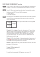
MOB ‘MAN OVERBOARD’ function MOB In case someone falls overboard, press the [MOB] key and hold for 2 seconds (or activate an external MOB switch - hold for 5 seconds). CLR Press [CLR] to confirm and reset the alarm if activated by mistake. ENT Before pressing [ENT] to start MOB navigation: • Reduce speed. • Turn off Autopilot. Press [ENT] to start MOB navigation with all relevant data available for an efficient rescue operation and a precise track record of the vessel’s movements.
CE34/44/54 ChartSounder Table of contents MOB ‘MAN OVERBOARD’ function ............................. back of front cover Chapter 1 Introduction and safety summary 1.1 Introduction and system familiarization ...................................... 1-1 1.2 Safety summary ........................................................................... 1-2 1.3 How to get started ........................................................................ 1-3 1.3.1 Dedicated function keys ...............................
Table of contents 3.4.9 3.5 3.5.1 3.5.2 CE34/44/54 ChartSounder PLOT menu ................................................................................ 3-15 Chart setup ..................................................................................3-17 Display modes in the chart setup ................................................3-18 Description of chart features ...................................................... 3-21 Chapter 4 Echo menu 4. Echosounder operation .............................
CE34/44/54 ChartSounder 6.3 6.4 6.5 6.6 6.7 6.7.1 6.8 6.9 Table of contents Decca lanes................................................................................... 6-5 Loran C.........................................................................................6-6 Satellite status............................................................................... 6-7 DGPS information........................................................................ 6-9 SDGPS information.........................
Table of contents CE34/44/54 ChartSounder Chapter 9 Troubleshooting, Maintenance and Service 9.1 Troubleshooting............................................................................ 9-1 9.2 Preventive maintenance................................................................ 9-2 9.3 Repair and service ........................................................................ 9-2 9.4 Specifications ...............................................................................
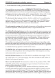
CE34/44/54 Introduction and safety summary Chapter 1-1 1.1 Introduction and system familiarization Congratulations on your purchase of SIMRAD CE34/44/54 ChartSounder - a combination of the latest GPS and SDGPS receiver technology and optional built-in differential receiver for accurate positioning, plus: detailed cartography and high performance echosounder; all in a unique slim-line design with a bright 7” TFT (CE34), 10” ATFT/TFT (CE44) or 15” TFT (CE54) color display.
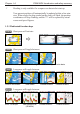
Chapter 1-2 CE34/44/54 Introduction and safety summary quick introduction to some of the features you have access to in your new chart sounder. The display examples shown in this manual are not always an exact copy of what you will see on the screen, as the presentation depends on your system configuration and choices of setup. How to interpret special marked key symbols etc. in the manual: +/- Either the + (plus) or - (minus) key may be applied. 0-9 Alpha-numeric keys for insertion of figures.
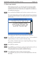
CE34/44/54 Introduction and safety summary Chapter 1-3 1.3 How to get started When starting up for the very first time, the first time after loading a new software or after a master reset: Make sure that all hardware installation and electrical connections are completed in accordance to the installation instructions. PWR Press and hold the [PWR] key until you have a picture on the screen The system will perform a software update and check for communication activity.
Chapter 1-4 CE34/44/54 Introduction and safety summary Heading is only available if a compass was detected at start-up. Your present position will automatically be updated within a few minutes. When ready, the ship symbol on the chart will flash, the position coordinates will stop flashing, and the *** will be replaced by actual course and speed figures. 1.3.
CE34/44/54 Introduction and safety summary PILOT Chapter 1-5 Short press will toggle between: Highway Position Dual Speed Set & Drift When navigation mode is active, these two displays will be included: ETA & AVN PILOT Long press will toggle between: Highway PAGE Trim & Highway Custom screen1 Custom screen2 Short press will toggle between the current active pages under the main function keys. Long press will start a rotation of the three pages (section 2.1).
Chapter 1-6 CE34/44/54 Introduction and safety summary 1.3.2 Chart and chart functions CHART Press the [CHART] key to call up a chart display. Press again to toggle between the chart shortcut series - see chart examples in section 1.3.1. C-MAP cartridges (standby) Press [MENU], [6], [CHART] whenever inserting or removing a C-MAP card. Select and adjust chart or echosounder range Press one of the numeric keys 1 - 9 to select a range (and chart level).
CE34/44/54 Introduction and safety summary Chapter 1-7 How to plot or insert waypoints and marks • With cursor OFF (press [CLR]) Press [PLOT] and choose from: [PLOT] Plot ship’s position as mark. [1] Insert ship’s position. You can change the lat/lon figures, the symbol and the symbol’s size and color. [3] Insert specific waypoint. Suggested name, symbol, etc. can be altered. [6] Plot ship’s position as target.
Chapter 1-8 CE34/44/54 Introduction and safety summary How to edit a route - rubberbanding • To move a point on the chart: 1. Place cursor on the point you wish to move. 2. Press [ENT], [1], [2]. 3. Move cursor to new location. 4. Press [ENT] to complete. • To insert a new point on the chart: 1. Place cursor on the leg where the new point is to be inserted. 2. Press [ENT], [1], [2]. 3. Move cursor to where the new routepoint is to be placed. 4. Press [ENT] to complete.
CE34/44/54 Introduction and safety summary Chapter 1-9 Advance or stop navigation • Press [GOTO], [1] to advance to next point in the route. • Press [GOTO], [3] to stop navigation. Start and stop track 1. Press [TRACK] to call up ‘Start track’ window. 2. Before tracking is started, you can give the track a new name, make changes to track interval, track line type and color. 3. Press [ENT] to start track. 4. When you wish to stop tracking, press [TRACK], [ENT].
Chapter 1-10 CE34/44/54 Introduction and safety summary 1.3.3 Echosounder / Fishfinder ECHO Press the [ECHO] key to call up an echosounder display. Press again to toggle between the echo shortcut series - see display examples in section 1.3.1. Select and adjust echosounder range Press one of the numeric keys 1 - 9 to select a fixed range. Key 9 will select the largest range and key 1 the smallest. Use the +/- keys to adjust range in smaller steps. Key 0 will select Auto Range.
CE34/44/54 Fundamentals & initial start-up Chapter 2-1 SIMRAD CE44 2.1 Fundamentals of the display and page system The CE34/44/54 ChartSounder has a multi-function screen and data presentation system with full screen and different types of split screens. The series of pages under the function keys (situated in a vertical row to the right of the display) will in most situations be sufficient information for the operator.
Chapter 2-2 CE34/44/54 Fundamentals & initial start-up Long press on the [PAGE] key will start a rotation of the three pages in intervals of 5 seconds (increase/decrease the time in [MENU], [6], [1]). Press any key to stop rotation. 2.1.1 Example of how to exchange a page in the PAGE system The three pages in the PAGE system are collected from the CHART, ECHO and PILOT menus in the sequence of which the function keys appear on the keypad ie.
CE34/44/54 Fundamentals & initial start-up Chapter 2-3 Highlight a function e.g. Route calculation in the WP/RTE menu. WIN Press [WIN] several times to check the screen image (situated to the far right in the top line of the menu bar) which windows the function can be placed into ENT Press [ENT] to enter the highlighted function into the highlighted window If the function text in the menu is red, the display will not be available for the selected window. 2.
Chapter 2-4 CE34/44/54 Fundamentals & initial start-up TRACK Shortcut to starting/stopping the track function. CHART Shortcut to Chart function. Short press will toggle between different data fields on chart. Long press will toggle between Chart in full screen, Dual Chart, and two custom screens. ECHO Shortcut to Echosounder functions. Long press will toggle between Echo display in full screen with A-scope, Dual Frequency (CE44/ 54), and two custom screens. PILOT Shortcut to Pilot displays.
CE34/44/54 Fundamentals & initial start-up Chapter 2-5 2.3 Menu bar MENU Toggles the menu bar on/off To fit the complete menu bar across the screen, some of the menus have been abbreviated. However, the last selected menu will be highlighted, and if it’s an abbreviation of the menu, then the complete menu title is written above the menu bar. WIN MISCELLANEOUS 1 CHART 2 ECHO 3 PILOT 4 MISC 5 WP/RTE 1 Wind 2 Speed diagram, etc. 6 SETUP Having selected e.g.
Chapter 2-6 CE34/44/54 Fundamentals & initial start-up 2.
CE34/44/54 Fundamentals & initial start-up Chapter 2-7 2.5 Choice of symbols Waypoints and other points appearing on the screen can be marked by one of 18 symbols + 8 event marks in small or large symbols: 2.6 Naming of routes, points etc. First select the key with the desired letter, then you can either repeat the keystrokes, which will toggle between e.g. A,B,C,1, or once you have selected one letter you can go back and forth in the alphabet by means of the +/- keys.
Chapter 2-8 CE34/44/54 Fundamentals & initial start-up Automatic input source setup Interface has not been set up! ∆ To start automatic input source setup, make sure that all connected products are turned ON, and press ENT. ∆ Start ENT ENT After making sure that all connected products are turned ON: Press [ENT] to start automatic input source setup, - if a new product is connected later on, refer to section 8.5 Interface setup.
CE34/44/54 Fundamentals & initial start-up Chapter 2-9 Select display language: MENU 6,1 Call up the menu bar, and... press [6], [1] to call up the language display Press up on the cursor to go to the bottom line in the display +/- Select language ENT Confirm entry 2.8 Turn power on Starting up for the first time, or after loading a new software, or after a master reset - see section 2.7.
Chapter 2-10 CE34/44/54 Fundamentals & initial start-up
CE34/44/54 Chart menu and INFO windows Chapter 3-1 3. Chart menu 1 CHART 1 Chart 2 Dual Chart 3 Custom screen 1 The displays obtained from this menu can easily be accessed from the main function key [CHART] see section 3.1. 4 Custom screen 2 For safety reasons, navigation with electronic charts should always be combined with authorized paper charts.
Chapter 3-2 CHART From any display: Long press on the [CHART] key will toggle between: Chart CHART CE34/44/54 Chart menu and INFO windows Dual Chart Custom screen 1 Custom screen 2 From full chart display: Short press on the [CHART] key will toggle between different presentations of the data field on the chart e.g.: 3.1.1 Data field on chart Chart range indicator (0.11nm) can be set ON/OFF in ‘Show range’ - section 3.5 Chart setup under General.
CE34/44/54 Chart menu and INFO windows Chapter 3-3 long, compass and depth indication, bearing and distance to either approaching point or cursor position; together with time and date in local or UTC. *)Refer to section 5.3 Status indicator and accuracy. 3.1.2 Ship symbol The ship symbol indicates the present position on the chart and the vector informs of the actual heading (input from compass) or true course (course over ground).
Chapter 3-4 CE34/44/54 Chart menu and INFO windows 3.1.
CE34/44/54 Chart menu and INFO windows Chapter 3-5 3.2 Dual Chart display It is possible to have two charts in different scales on the screen at the same time, one for detail and one for overview. Each chart can be operated individually, and each will have its own cursor and individual chart setup. MENU 1,2 Call up the menu bar, and... press [1] and [2] to call up the Dual Chart display WIN Press the [WIN] key to select active display (red frame).
Chapter 3-6 CE34/44/54 Chart menu and INFO windows 3.3 Chart custom screens The two custom screens in the chart menu consist of multiple window combinations e.g.: The displays, which are not related to the chart function, can be exchanged with a different one. It is also possible to change the right half of the screen from two quarter windows to half screen window, and vice versa. See section 2.1.2 how you go about changing the displays.
CE34/44/54 Chart menu and INFO windows Chapter 3-7 3.4 Chart quick menu Access the chart quick menu from active chart display. The functions available depends on the actual situation - refer to sections 3.4.1 to 3.4.7. 3.4.
Chapter 3-8 CE34/44/54 Chart menu and INFO windows 3.4.
CE34/44/54 Chart menu and INFO windows Chapter 3-9 3.4.3 Cursor placed on waypoint ENT With chart in active window, and cursor placed on a waypoint, press [ENT] to call up the quick menu with the following to choose from: WP found Name: WP 1 LAT 57°15.504N LON 9°17.249E 1 Edit user data 2 Chart info Refer to Appendix C 3 Find nearest port services Refer to Appendix C 4 Bearing and dist from A to B Refer to section 3.4.2 5 Lock cursors Refer to section 3.4.
Chapter 3-10 CE34/44/54 Chart menu and INFO windows 3.4.4 Cursor placed on route leg or line section ENT With chart in active window, and cursor placed on a route leg or line section, press [ENT] to call up the quick menu with the following to choose from: Route leg found: Name: RTE 1 Leg: B130° 34.26nm Total: 5 legs 143.1nm 5-6 1 Edit user data 2 Chart info Refer to Appendix C 3 Find nearest port services Refer to Appendix C 4 Bearing and dist from A to B Refer to section 3.4.
CE34/44/54 Chart menu and INFO windows Chapter 3-11 3.4.5 Cursor placed on routepoint or linepoint ENT With chart in active window, and cursor placed on a routepoint or linepoint, press [ENT] to call up the quick menu with the following to choose from: Routepoint found Name: RTE 1 From start: 108.8nm To end: 34.26nm 5 1 Edit user data 2 Chart info Refer to Appendix C 3 Find nearest port services Refer to Appendix C 4 Bearing and dist from A to B Refer to section 3.4.
Chapter 3-12 CE34/44/54 Chart menu and INFO windows 3.4.6 Cursor placed on trackpoint Trackpoints are not as easily recognized as Routepoints, you may have to move the cursor along on the track to locate a trackpoint.
CE34/44/54 Chart menu and INFO windows Chapter 3-13 3.4.7 Cursor placed on target ENT With chart in active window, and cursor placed on a target symbol, press [ENT] to call up the quick menu with the following to choose from: Target found Name: TARGET 1 LAT 57°02.825N LON 7°45.555E 1 Edit user data 2 Chart info Refer to Appendix C 3 Find nearest port services Refer to Appendix C 4 Bearing and dist from A to B Refer to section 3.4.2 5 Lock cursors Refer to section 3.4.
Chapter 3-14 CE34/44/54 Chart menu and INFO windows 3.4.8 GOTO menu GOTO Call up the GOTO menu with access to navigation modes: Select NAV mode 1 Cursor 2 Waypoint 3 Route 4 Track 5 Anchor guard To select “Cursor” navigation will require that the chart cursor is active. “Waypoint”, “Route” and “Track” navigation requires that a waypoint, route or track is stored in the memory. MENU Exit For further details on the different NAV modes, refer to section 5.9 Navigation examples.
CE34/44/54 Chart menu and INFO windows Chapter 3-15 3.4.9 PLOT menu The CEXX is designed to make navigation easy and safe. Waypoints can easily be plotted with a single keystroke, or be inserted via the keypad. Making routes and drawing lines are done directly on the chart. Very straightforward, uncomplicated and with a high level of confidence as you can follow your actions ‘live’ on the chart.
Chapter 3-16 CE34/44/54 Chart menu and INFO windows the keypad, change the location name (cf.section 2.6), or change the symbol (cf.section 2.5) and the color (select with +/- keys). Any changes made will be new presets for plotting/insertion of the cursor position. - From active chart display with cursor on: Same options as above, except that the zeroes in the position coordinates have been exchanged with the cursor position. - From active echo display: Plot and save waypoint from echogram.
CE34/44/54 Chart menu and INFO windows Chapter 3-17 3.5 Chart setup The settings are dedicated to the chart in the active window and does not affect the second chart in dual chart mode. ADJ Load chart setup related to active chart ◄ GOTO General Presentation Dep Display mode Orientation Rotation resolution Motion NORTH UP 15° RELATIVE Quick chart info Cursor 5 min.
Chapter 3-18 CE34/44/54 Chart menu and INFO windows +/- Toggle between available settings ENT Confirm changes and return to chart, or... MENU Abandon Chart setup and return to chart without making any changes 3.5.1 Display modes in the chart setup There are 6 different display modes to choose from: FULL (default), CUSTOM, SIMPLE, FISHING, LOW, and GRID mode. When a group is shown in red or a function is shown in light grey it means that it is not available in the selected display mode.
CE34/44/54 Chart menu and INFO windows Chapter 3-19 .....continued from previous page.... C-MAP features Land: Natural features rivers Natural features Cultural features Landmarks Chart: Grid Boundary lines Mixing levels Declutter Full *Custom Simple Fishing Low ON ON ON ON ON ON ON ON ON OFF OFF ON OFF OFF OFF OFF OFF OFF OFF OFF AUTO AUTO ON ON AUTO AUTO OFF ON AUTO AUTO OFF ON AUTO OFF ON ON AUTO OFF OFF ON Group: Depth - specifies the presentation of depth lines, levels, etc.
Chapter 3-20 CE34/44/54 Chart menu and INFO windows Group: Areas - defines the presentation of different areas on chart. The default settings in this group are the same for all display modes, except GRID, which do not include C-MAP features. The features can be changed from FILLED to CONTOUR: C-MAP features Land areas Depth areas Caution areas Dredged areas All display modes FILLED FILLED FILLED FILLED Group: User data - user defined objects can be visible or invisible on chart.
CE34/44/54 Chart menu and INFO windows Chapter 3-21 3.5.2 Description of chart features Auto chart select - When sailing with ‘Auto chart select’ ON and cursor turned off, the range will automatically change to match the chart which is available. But when set to OFF, then the selected range will remain, also when sailing ‘out of the chart’. Boundary lines - will indicate available C-MAP chart areas. Caution areas - can be set to FILLED or CONTOUR.
Chapter 3-22 CE34/44/54 Chart menu and INFO windows Land areas - can be set to FILLED or CONTOUR. FILLED= The land areas will be filled with a preset color in the Palette setup. CONTOUR= The land areas will be shown with a contour line only and the landfill will be the same as the background/water color on the chart. Land settings - can all be set ON=Shown on chart or OFF=Not shown on chart. Marine settings - can all be set ON or OFF, except for Nav-Aids which can be set to INTERNATIONAL, INT.
CE34/44/54 Chart menu and INFO windows Chapter 3-23 Show range - can be set to WITH BACKGROUND, ON or OFF: WITH BACKGROUND - will add a small line to the chart display indicating that the length of the line equals a certain number of nautical miles/km - the indication is highlighted with a background color. ON - same as above, but without background color. OFF - indication is not shown on chart. Soundings - can be set to ON or OFF. ON - the information will be shown as selected i.e.
Chapter 3-24 CE34/44/54 Chart menu and INFO windows
CE34/44/54 Echo menu Chapter 4-1 4. Echosounder operation The echosounder function of the CEXX determines the distance between its transducer and underwater objects such as fish, lake bottom or sea bed. It does this by utilizing the fact that an ultrasonic wave transmitted through water travels at a nearly constant speed of 4800 feet (1500 meters) per second. When a sound wave strikes an underwater object such as fish or sea bottom, part of the sound wave is reflected back toward the source.
Chapter 4-2 CE34/44/54 Echo menu 4.1 Echo menu 2 ECHO 1 50kHz (or 38kHz CE44/54) 2 200kHz 3 Dual frequency (CE44/54) 4 Custom screen 1 5 Custom screen 2 Low and high frequency echosounder display can be set up separately. The low frequency display will show deep water bottom contours, and the high frequency display will show the mid-water section with trawl targets or bait fish in a higher resolution.
CE34/44/54 Echo menu ECHO Chapter 4-3 From any display: Long press on the [ECHO] key will toggle between: 200kHz Dual Frequency (CE44/54) Custom screen 1 Custom screen 2 4.3 Standard echo display This is the basic presentation mode (standard display) for observing fish schools and sea bed. Some surface noise may appear just below the transmission line. Transmission line. Time scale. Depth range is adjustable with +/- keys or the Quick-range keys 1-9. Press key 0 to return to Auto range.
Chapter 4-4 1-9 Select range in 9 steps +/- Adjust range with the + and - keys 0 CE34/44/54 Echo menu Activate Auto range Press cursor left/right to adjust gain ADJ Direct access to Setup display related to active echo display 50kHz or 200kHz - (see section 4.7) Use the cursor to go to the function you wish to change the value for +/- Toggle between available values ENT Confirm changes, or... MENU Abandon changes and exit Setup display 4.
CE34/44/54 Echo menu Chapter 4-5 4.5 Echo quick menu A number of echo features can easily be accessed from the Echo quick menu.
Chapter 4-6 CE34/44/54 Echo menu the expansion window can be adjusted in the Setup display. 5 Zoom display This feature will provide an expanded view of the area near the *Variable Range Marker which will give a better separation of echoes. The actual range of the expansion window can be adjusted in the Setup display. *) see section 4.4. 6 Shift display This feature can be applied when operating in deep waters. Select the range for an expansion window.
CE34/44/54 Echo menu Chapter 4-7 4.7 Presentation setup The general Echosounder setup e.g. Selecting transducer, Alarm settings, Demo mode etc. is placed in the SETUP menu (section 8.2). The echo setup in this chapter are the most common settings for adjusting the presentation of the high or low frequency echo picture, and can be accessed by a single keystroke.
Chapter 4-8 CE34/44/54 Echo menu the display screen. Selecting Auto range will cause the CEXX to change the basic range setting(s) to keep the displayed bottom in the lower half of the display. For instance, as your boat moves into deeper waters, the system will automatically switch to a deeper range, always keeping the displayed bottom in the lower half of the display. Manual range allows the operator to set the range displayed on the screen.
CE34/44/54 Echo menu Chapter 4-9 echoes received and only reflect on the screen what is received from both echoes, which will give a more uncluttered recording. Signal threshold – can be set to ON to eliminate the appearance of unwanted noise. The threshold level is automatic and the feature should be used with caution, as it may eliminate small fish and small unidentified objects on the screen.
Chapter 4-10 CE34/44/54 Echo menu 4.8 How the echosounder works When the CEXX is turned on, a transmitter begins to send electrical pulses to the transducer. The ceramic resonators in the transducer has a special property which enables it to change dimensions slightly when a varying voltage is applied. The voltage is thus converted to mechanical vibrations (sound waves) which are then transmitted down through the water. See Fig. 1. Fig. 1 Transmi ed ‘ping’ from the transmi er/receiver.
CE34/44/54 Echo menu Chapter 4-11 4.9 Transducer beamwidth The transducer mounted to the hull of your vessel serves as both a ‘speaker’ when transmitting, and as a ‘microphone’ when the echosounder is receiving. Similar to the way a flashlight focuses light, most of the sound from your transducer is focused downwards with a smaller amount going out to the sides. The amount of focusing of the sound beam is expressed as a ‘beamwidth’.
Chapter 4-12 CE34/44/54 Echo menu 4.10 Effects of the vessel’s speed The presentation of fish on the CEXX depends directly on the vessel’s speed, as well as on the depth of the fish. When the vessel is at rest, the echo traces will appear stretched and flattened. As the vessel’s speed becomes greater, the echo traces will become shorter and more arched. The reason for this change in appearance is that as the vessel speed increases, fewer number of sound ‘pings’ strike each fish.
CE34/44/54 Pilot menu & navigation examples Chapter 5-1 5. Pilot menu 3 PILOT 1 Highway - see section 5.2 & 5.2.1 2 Position - see section 5.3 3 Dual Speed - see section 5.4 4 ETA & AVN - see section 5.5 5 Trim & Highway - see section 5.6 6 Set & Drift - see section 5.7 7 Custom screen 1 - see section 5.8 8 Custom screen 2 - see section 5.8 See also section 5.10 Anchor guard, section 5.11 MOB navigation and 5.9 Navigation examples.
Chapter 5-2 PILOT CE34/44/54 Pilot menu & navigation examples Press the [PILOT] key from any display to call up a display in the pilot-series, and: Long press on the [PILOT] key will toggle between (default): Highway PILOT Custom screen 1 Custom screen 2 From one of the pilot displays i.e.
CE34/44/54 Pilot menu & navigation examples Chapter 5-3 5.2 Highway display and Navigation setup MENU 3,1 Call up the menu bar, and... load Highway display When there is no navigation mode active, you will receive the legend: NAVIGATION IS OFF. Before starting out in one of the navigation modes, it may be a good idea to check out the Navigation setup display and see if the default settings will suit your need. ADJ Load Navigation setup Navigation setup: Anchor alarm distance: 00.
Chapter 5-4 CE34/44/54 Pilot menu & navigation examples The waypoint alarm will be activated when you reach the circle or the perpendicular line - WP line alarm - crossing through the waypoint. When “Auto waypoint shift” is set to “WP-circle” it will override the “WP circle alarm” function. XTE alarm - forms a corridor along the ideal track. When crossing one of the boundaries the XTE alarm will be activated. The alarm will automatically reset once you are inside the limits again.
CE34/44/54 Pilot menu & navigation examples Chapter 5-5 5.2.1 Highway display when navigation mode is active MENU 3,1 Call up the menu bar, and... load Highway display With navigation mode active, the highway display will provide a graphical steering display: Intended track between two waypoints. XTE alarm lines - refer to sec.5.2 for alarm setup. Ship’s position and course in relation to intended track.
Chapter 5-6 CE34/44/54 Pilot menu & navigation examples 5.3 Position display MENU 3,2 Call up the menu bar, and... load the Position display Datum currently selected. Trip log 1 and 2. Position with three decimals in minutes. Speed over ground. Course, magnetic or true. Internal POS 15-03-2004 Depth or Compass from external sensor. UTC or local time and date - Time and date in UTC - Universal Time Coordinates - is equal to standard time in London (GMT).
CE34/44/54 Pilot menu & navigation examples Chapter 5-7 Status indicator and accuracy Small letters (a,b,c,) indicate that SA is active, and the position accuracy is expected to be better than 100 meters in 95% of the time. Capital letters indicate that SA is OFF, and the position accuracy is then expected to be 15 meters or better in 95% of the time. dGPS indicates that differential data is received, either via built-in differential receiver or from external receiver.
Chapter 5-8 CE34/44/54 Pilot menu & navigation examples 0-9 +/- Key in new values, or... Toggle between available values ENT Confirm editing and return to the Position display Datum - is preset to WGS 1984 (World Geodetic System 1984), but can be changed to any of the 118 datums listed in Appendix B e.g. to match old paper charts or trackplotter data from RS2500/RS4000 (datum #002 European 1950). The position in the position display and NMEA output (GLL+GL2) will refer to the selected datum.
CE34/44/54 Pilot menu & navigation examples Chapter 5-9 5.4 Dual speed display (trawling speed display) The analogue differential speed indicator will show how much the present speed varies from the average speed. If the difference exceeds +/- 3 knots (or km/h or miles/h), an arrow will appear which will be pointing out of the scale. MENU 3,3 Call up the menu bar, and... load Dual Speed display Internal POS Water speed readout from connected log transducer. Position with three decimals in minutes.
Chapter 5-10 CE34/44/54 Pilot menu & navigation examples 5.5 ETA & AVN display MENU 3,4 Call up the menu bar, and... load the ETA & AVN display -to receive any data will require that navigation mode is active. ETA - Estimated Time of Arrival - refers to the inserted local time, and can be calculated to any point used for navigation. AVN - Approximate Velocity Necessary - is automatically calculated in knots after you key in the planned arrival time and date.
CE34/44/54 Pilot menu & navigation examples Chapter 5-11 Go to AVN, and... 0-9 Insert time and date ENT Confirm entry 5.6 Trim & Highway display Some of the readings rely on data from external log and compass. The Trim & Highway display will provide information on actual and mean speed, velocity and water speed - see also section 5.7 Set & Drift display. MENU 3,5 Call up the menu bar, and... load the Trim & Highway display B: Bearing. X: XTE Cross-trackerror. D: Distance to point.
Chapter 5-12 CE34/44/54 Pilot menu & navigation examples 5.7 Set & Drift display MENU 3,6 The readings rely on data from external log and compass. Call up the menu bar, and... load the Set & Drift display Relative direction. True direction. Speed. The Set & Drift display will show how fast the current is moving in knots; in what direction (true) it is moving and what direction in relation to the vessel (relative).
CE34/44/54 Pilot menu & navigation examples Chapter 5-13 5.8 Pilot custom screens The two custom screens in the pilot menu consist of multiple window combinations e.g.: The displays presented in the example above are the default displays for Custom screen 1 under the PILOT menu.
Chapter 5-14 CE34/44/54 Pilot menu & navigation examples 5.9 Navigation examples 5.9.1 Chart/cursor navigation. 5.9.2 Waypoint navigation. 5.9.3 Route navigation. 5.9.4 Track navigation. Relevant for all navigation modes are: - the highway display with graphical steering - section 5.2.1. - the ETA & AVN display with Estimated Time of Arrival and Approximate Velocity Necessary to reach a given point at a specific time - section 5.5.
CE34/44/54 Pilot menu & navigation examples Chapter 5-15 Next destination: While on the way, you can easily move the cursor to the next destination, and when ready to change navigation leg... GOTO 2 Call up the GOTO menu Restart to approaching point - a new course line will be drawn from ship’s position to destination. To turn NAV mode off again: Press [GOTO], [3]. 5.9.2 Waypoint navigation To start Waypoint navigation will require that at least one waypoint is stored in the memory. Refer to section 3.
Chapter 5-16 CE34/44/54 Pilot menu & navigation examples 5.9.3 Route navigation To start Route navigation will require that at least one route is stored in the memory. Refer to section 3.4.9 PLOT menu. There are two ways to start Route navigation: • From the chart: Place cursor on the routepoint you wish to start your navigation from GOTO 3 Call up the GOTO menu, and...
CE34/44/54 Pilot menu & navigation examples Chapter 5-17 routepoint. GOTO Pressing [GOTO] from chart display during navigation will activate an INFO window with the following functions to choose from: 1. Advance (to next routepoint) 2. Restart to approaching point (in case you have drifted off course) 3. Turn NAV OFF 5.9.4 Track navigation A track is created by a series of trackpoints connected by track lines. Using a track for navigation is somewhat like navigating in a route with many waypoints.
Chapter 5-18 CE34/44/54 Pilot menu & navigation examples This will activate the pop-up window “Navigate in track” from where you can choose which track you wish to select for navigation: +/- Scroll up/down in the track list until the correct track number / name appears Use the cursor to move around in the window if anything needs to be changed - such as Direction in track, etc.
CE34/44/54 Pilot menu & navigation examples Chapter 5-19 5.10 Anchor guard GOTO 5 Call up the GOTO menu, and... activate the anchor guard function -the chart display will provide an impression of the vessel’s position in relation to the alarm circle. 3,1 To check/change the preset alarm distance: Call up the menu bar, and...
Chapter 5-20 CE34/44/54 Pilot menu & navigation examples
CE34/44/54 Miscellaneous menu Chapter 6-1 6. Miscellaneous menu 4 MISC 1 Wind - see section 6.1 2 Speed diagram - see section 6.2 3 Decca lanes - see section 6.3 4 Loran C - see section 6.4 5 Satellites - see section 6.5 6 DGPS - see section 6.6 7 SDGPS - see section 6.7 8 DSC info - see section 6.8 9 Depth & temperature diagram - see section 6.9 6.1 Wind display The CEXX is ready to present wind data from connected instruments. MENU 4,1 Call up the menu bar, and...
Chapter 6-2 ADJ CE34/44/54 Miscellaneous menu Load Setup for Wind display Setup for Wind: Damping level: MEDIUM Apparent wind scale: NORMAL Wind angle offset: 000° Show wind speed as: Wind speed unit: APPARENT METERS/SECOND Go to the function you wish to change +/- Toggle between settings, or... 0-9 Key in new figure ENT Confirm entry and return to Wind display Damping level - can be set to LOW, MEDIUM or HIGH. The higher level the more steady and slow reacting reading.
CE34/44/54 Miscellaneous menu Chapter 6-3 6.2 Speed diagram MENU 4,2 Call up the menu bar, and... load “Speed diagram” S= Speed over ground. V= Velocity towards waypoint. W*= Speed through water. SD (Set and drift)*= Speed and direction, true or relative. WIND*= Speed and direction. * Connection to external sensors is required. ADJ Call “Speed diagram setup” - see next page.
Chapter 6-4 CE34/44/54 Miscellaneous menu The scale for the speed diagram can be adjusted in this display. Time interval can be set in 8 intervals from 1 minute to 3 hours and freeze.
CE34/44/54 Miscellaneous menu Chapter 6-5 6.3 Decca lanes MENU 4,3 Call up the menu bar, and... load decca chain display ADJ Open for change +/- Leaf through the available chains - see below. ENT Confirm entry To change the position readouts to decca mode, see section 8.3 under Pilot/Position setup, where ‘Display position as’ can be toggled to ‘Decca’.
Chapter 6-6 CE34/44/54 Miscellaneous menu 6.4 Loran C MENU 4,4 Call up the menu bar, and... load Loran C chain display ADJ Open for change +/- Leaf through the available chains - see listing below. If required, go to the slaves, and... +/- Toggle between available slaves (not all chains have more than one slave) 0-9 ...
CE34/44/54 Miscellaneous menu Chapter 6-7 6.5 Satellite status MENU 4,5 Call up the menu bar, and... load satellite status display The display will show which satellites are currently being used for computation of data. It will show their position together with SNR - Signal to Noise Ratio. The bottom line shows the status of all the satellites in the GPS system, starting from left to right with the numbers 1 to 32. Satellite status (bottom line): + indicates the satellite is healthy.
Chapter 6-8 CE34/44/54 Miscellaneous menu Position update alarm “Alarm” in the satellite status display is preset to “OFF”. If the received position data is invalid, the position shown in the position display will start to flash. A position update alarm can be set ON/ OFF from the satellite status display [MENU],[4],[5]: ADJ Open for change Go to “Alarm” +/- Toggle alarm ON/OFF ENT Confirm entry Reset the alarm by [CLR]. Status indicator: GPS* - see section 5.3.
CE34/44/54 Miscellaneous menu Chapter 6-9 6.6 DGPS information (optional) MENU 4,6 The DGPS - differential position corrections - can be provided from a built-in module, which is preset to full automatic operation, or from connected DGPS receiver - see “Status indicator” in position display. List of beacon stations is available in addendum, part no. 183-0122-501. Call up the menu bar, and...
Chapter 6-10 CE34/44/54 Miscellaneous menu Status - can either be: LOCKED = locked on a beacon and receiving differential data. NOT LOCKED = not locked on a becon and receiving no differential data. NOT INSTALLED = there is no built-in DGPS module in unit. NOT IN USE = external DGPS receiver applied. Beacon is monitored - YES or NO. If YES it should be safe to rely on the received differential data, because the beacon station’s performance is under observation.
CE34/44/54 Miscellaneous menu Chapter 6-11 6.7 SDGPS information The SDGPS - satellite differential GPS - is preset to full automatic operation, which means that the system will utilize the position corrections from either differential GPS stations (refer to section 6.6) or satellite differential GPS signals from WAAS, EGNOS or MSAS (refer to section 6.7.1). MENU 4,7 Call up the menu bar, and... load SDGPS setup display SDGPS setup: SDGPS select mode: Uses corrections from: CHANNEL 1: sat.no.
Chapter 6-12 CE34/44/54 Miscellaneous menu Uses corrections from - indicates which differential corrections (DGPS or SDGPS) are currently used for position determination. CHANNEL 1: sat.no. - indicates which satellite number and name is currently tracked/searched by channel 1, and what is the tracking state. Corrections - indicates if corrections are being received on this channel. If YES: is the quality of the reception sufficiently high for the corrections to be usable.
CE34/44/54 Miscellaneous menu Chapter 6-13 6.7.1 Satellites in SDGPS system The SDGPS system consist of eight orbiting geostationary satellites and is designed to form a seamless global augmentation system consisting of Waas (USA), EGNOS (Europe) and MSAS (Japan). If all three parts would become operative at the same time, there would be no performance problem.
Chapter 6-14 CE34/44/54 Miscellaneous menu 6.8 DSC VHF info To receive an iDSC Alarm and Message from VHF will require that the CEXX is connected to a compatible Simrad VHF radiotelephone. The data is transmitted via NMEA or SimNet. The message from the VHF will appear in a pop-up window together with an acoustic alarm. Press [CLR] to reset the alarm, or press [ENT] to stop alarm and select the suggested channel for communication - refer to the VHF manual for further details.
CE34/44/54 Miscellaneous menu Chapter 6-15 6.9 Depth & temperature diagram MENU 4,9 Call up the menu bar, and... activate Depth & temperature diagram Present water temperature and depth. Depth over time or distance. Temperature over time or distance. ADJ Call Setup for Depth Setup for Depth: Scale for depth: 0 -> 100 m Color for depth: Scale for temperature: Color for temperature: Interval of screen: Time interval: Go to the function you wish to change 0 -> 20 °C TIME 5 MIN.
Chapter 6-16 0-9 +/- Key in new figures, or... change settings ENT Confirm changes CE34/44/54 Miscellaneous menu Scale for depth - there are six depth scales to choose from, ranging from 0 -> 10m to 0 -> 3000m. Toggle between values with +/- keys. Color - for depth and temperature can be changed. Toggle between available colors by means of the +/- keys. Scale for temperature - can be set to 0 -> 10°, 0 -> 20°, 0 -> 30°, 10 -> 20°, and -10 -> 10°.
CE34/44/54 Waypoint / route menu Chapter 7-1 7. Waypoint / route menu 5 WP/RTE 1 Waypoints - see section 7.1 2 Routes - see section 7.2 3 Route calculation - see section 7.3 4 Lines - see section 7.4 5 Tracks - see section 7.6 6 Targets - see section 7.7 7 MOB data - see section 7.8 8 Data transfer - see section 7.9 + 7.10 7.1 Waypoints stored in the memory The waypoint list will appear in alphabetical order and will include the waypoint’s position in lat/long.
Chapter 7-2 CE34/44/54 Waypoint / route menu A-Z Insert name of waypoint you wish to edit, or... +/- Leaf through waypoints with +/- keys or up/down cursor ENT Open for editing Place the cursor on the function you wish to change 0-9 +/- Key in new figures, or... toggle between available values PLOT Move the position to ship’s position ENT Confirm entry and return to WP list Plot new waypoints with the [PLOT] key - refer to section 3.4.9. 7.1.
CE34/44/54 Waypoint / route menu Chapter 7-3 7.2 Routes stored in the memory The route list will keep a record of all the saved routes in the system. It will provide information on number of waypoints in the route etc. Existing routes can be altered via the route list - see further on in this chapter, or directly on the chart via info windows - refer to sections 3.4.4 and 3.4.5. To delete a route - refer to section 7.2.1.
Chapter 7-4 CE34/44/54 Waypoint / route menu This display provides information on course line, XTE line, route legs, routepoints etc. ENT Call up the Edit route display - if you wish to make any changes. (Editing a route currently used for navigation is not possible) Setting the Course line to OFF in this display will make the route invisible on the screen. Put it back on the screen by setting it ON again.
CE34/44/54 Waypoint / route menu Chapter 7-5 If the XTE distance is not the same in all legs, the value will be *.* instead of the 00.10nm. Navigation mode can be either RHUMBLINE or GREAT CIRCLE, or... if not set to the same in all legs in a route, the mode will be: COMPOSITE. Direction in route can be set to either FORWARD or REVERSE direction.
Chapter 7-6 CE34/44/54 Waypoint / route menu 7.2.1 Delete route via menu MENU 5,2 Call up the menu bar, and... load route list display +/- Select the route you wish to delete ENT Call up the details on highlighted route ENT Open for editing WIN Delete route CLR Confirm that you want to delete the selected route, if not sure: press [MENU] to exit the display without having made any changes. Edit routes directly on the chart via info windows, refer to section 3.4.4 and 3.4.5. 7.2.
CE34/44/54 Waypoint / route menu Chapter 7-7 the +/- keys and then press [CLR] to remove the point from the route. Display example: ENT Save the route with [ENT] and go to the Edit display - or leave the function with [MENU] to abandon the route. In the Edit route display you can set up the route preferences you need and also change the name of the route. Place the cursor on the function you wish to change 0-9 +/- Key in new figures, and...
Chapter 7-8 CE34/44/54 Waypoint / route menu 7.3 Route calculation To stay well informed during navigation, the Route calculation display will provide information on how long it takes to go from one point to another, total distance, arrival time etc. MENU 5,3 +/- Call up the menu bar, and... load route calculation display Toggle between available routes in the memory Go to Routepoint A, and...
CE34/44/54 Waypoint / route menu Chapter 7-9 7.4 Lines stored in the memory The line list will keep a record of all the saved lines in the system. It will provide information on number of line sections in line etc. ‘Lines’ are used for defining a certain area on the chart e.g. a fishing ground, a shipwreck, large rocks, restricted areas etc., or defining a channel to sail through narrow passages, making your own coast line or for whatever reason you could use a drawing on the chart.
Chapter 7-10 CE34/44/54 Waypoint / route menu Leaf through the line points by moving cursor up/down ENT Call up the Edit line display - if you wish to make changes. Turning “Line” OFF will make the line drawing invisible on the screen. Put it back on the screen by turning it ON again. Place the cursor on the function you wish to change i.e. name, line type or color +/- Toggle between available values ENT Confirm editing MENU Return to line list 7.4.
CE34/44/54 Waypoint / route menu Chapter 7-11 7.5 Start / stop track The track function will provide a track trailing the movement of your ship. As default from the factory, the first track is stored as TRACK 1, the next as TRACK 2 etc. To start track function: TRACK Load Start track pop-up window If you wish to change the default values: Move cursor to where you wish to make a change +/0-9 Toggle between available values, or... key in new values ENT Start track Name of track can be altered (max.
Chapter 7-12 CE34/44/54 Waypoint / route menu Type of track line i.e. full, dotted, etc. has 9 different types to choose from in 15 different colors. To stop track: TRACK ENT Load Stop track pop-up window Stop the highlighted track 7.6 Tracks stored in the memory All tracks (of more than 1 trackpoint) will automatically be stored in the memory. To see which tracks are registered, you can scroll through the list by: MENU 5,5 Call up the menu bar, and...
CE34/44/54 Waypoint / route menu ENT Chapter 7-13 Open for change “Display track” can be set ON/OFF, where OFF will make it invisible on the screen. Turn ON to put it back on the screen. +/- Toggle between available values ENT Confirm changes MENU Return to track list 7.6.1 Delete tracks via menu MENU 5,5 Call up the menu bar, and...
Chapter 7-14 CE34/44/54 Waypoint / route menu 7.7 Targets stored in the memory The CEXX can display the bearing and distance of up to three targets at a time in relation to the vessel e.g. harbors or important navigational points. A target is a fixed point on the chart which can be plotted by the cursor or from the ship’s position - refer to section 3.4.9, or keyed in via the keypad - refer to section 3.4.7.
CE34/44/54 Waypoint / route menu +/- Toggle between available values ENT Confirm entry Chapter 7-15 7.7.1 Delete target via menu MENU 5,6 Call up the menu bar, and... load target display +/- Select the target you wish to delete ENT Open for editing WIN Delete target CLR Confirm that you want to delete the selected target, if not sure: press [MENU] to exit the display without having made any changes. Edit targets directly on the chart via info windows, refer to section 3.4.7. 7.
Chapter 7-16 CE34/44/54 Waypoint / route menu 7.9 Data transfer via DataCard or disc Data transfer to and from external memory can be performed via Simrad DataCard (CE34/44/54), or with a Simrad TL50 Turbo Loader (CE44/54) via an ordinary 1.44Mb disc. DataCards and TL50 Turbo Loader are optional equipment available from your local Simrad dealer. How to perform data transfers via TL50 (including data from Shipmate RS2500 Trackplotter) is described in the TL50 manual.
CE34/44/54 Waypoint / route menu 1 3 Chapter 7-17 DataCard status Press [1] to find out what data (if any) is stored on the DataCard The capacity is divided into two databanks: DATABANK 1 and 2 which can hold approx. 2 x 450 Kb data. Toggle between the two databanks with the +/- keys. Save on DataCard Press [3] to call up a new INFO window where you can see which data will be transferred i.e. routes, waypoints, etc. and how much space it will take up in bytes + percentage of max. storage capacity.
Chapter 7-18 CE34/44/54 Waypoint / route menu User data generated by other chartplotter models e.g. CE33/40/42/52, CP33/40/42/52, CA40/42/52, CR40/42/52 can all be transferred to a CE34/44/54 unit via the Data transfer system. However, it is not immediately accessible to transfer data via DataCard from the new model CE34/44/54 to the older model CE42, etc., as this would require an update of the CE42. - For more information, please contact an authorized Simrad dealer.
CE34/44/54 Waypoint / route menu MENU Chapter 7-19 Press [MENU] to exit and *reboot (only if loading “Setup”) *) When the system makes a ‘reboot’ the screen will turn black for a brief moment, then the system will re-start and automatically return to the active display which was on the screen before you made the transfer. 7.9.1 List of criteria for data transfer in the Action column OVERWRITE - will overwrite existing data in the memory you are transferring data to.
Chapter 7-20 CE34/44/54 Waypoint / route menu 7.10 Data transfer via PC interface Data transfer to and from a route planning program on a Personal Computer can be made via NMEA connection (Refer to Optional connections in the Installation manual) by means of the standard NMEA0183 sentences WPL and RTE. The data transfer on these two sentences does not include WP symbol, color, XTE limit, etc. PC-based planning systems differ in operation and performance beyond the control of Simrad.
CE34/44/54 Waypoint / route menu Chapter 7-21 CE34 example: WARNING! Normal NMEA communication will be interrupted. MENU Exit Accept ENT Press [ENT] to accept warning and continue. NMEA (1) connection 1 Transmit WPs 3 Transmit routes 7 Receive WPs and routes MENU Exit 1 Transmit WPs Press [1] to start transmission of all waypoints stored in the CEXX WP list to PC When the transmission is completed you will receive a new info window informing of how many waypoints were transferred.
Chapter 7-22 7 CE34/44/54 Waypoint / route menu Receive WPs and routes Press [7] to enable reception of waypoints and routes from the planning program The transmission of waypoints and routes can now be activated from the PC program. The info window below will inform you of the progress of the reception of data by keeping an eye on the counter. When the counter stops, means that all the data from the PC planner has been collected.
CE34/44/54 Setup menu Chapter 8-1 8. Setup menu 6 SETUP CHART C-MAP cartridges - see section 8.1 ECHO Echosounder setup - see section 8.2 PILOT Pilot/Position setup - see section 8.3 1 Speed alarm, units & language - see section 8.4 2 Interface setup - see section 8.5 3 Palette setup - see section 8.6 4 Factory settings - see section 8.7 5 QuickGuide - see section 8.8 8.
Chapter 8-2 CE34/44/54 Setup menu To open the drawer below the keypad, press the eject key next to the drawer. Place the cartridge in the tray with the terminals pointing towards the unit, and push the drawer back in place - make sure it is closed tight, so it remains watertight. ENT MENU Press [ENT] to test the data on the C-MAP C-card If a C-card is defect, it must be removed before you can exit the display.
CE34/44/54 Setup menu Chapter 8-3 CE34 example: Echosounder setup: SINGLE 200kHz Transducer: 00.0 m Keel depth below surface: 00.0 m Display: DEPTH BELOW KEEL Data on NMEA-out from: NONE Alarm for fish: Strength: 065% OFF Depth DS fish: min: 0005 m max: 0030 m Depth DK alarm min.: 0005.0 m OFF Depth DK alarm max.: 0030.0 m OFF Water profile: SALT Velocity of sound in water: 1470m/s Time/distance scale: ON Restart of AUTO pulse/power: 20 sec.
Chapter 8-4 +/- Select new values by means of the +/- keys ENT Confirm changes, or... MENU CE34/44/54 Setup menu Abandon changes and exit display Transducer - select transducer type. Insert the depth (position) of the transducer below surface. Display can show: DEPTH BELOW KEEL / SURFACE / TRANSDUCER Data on NMEA-out from - select the frequency you wish to use for transfer of data to connected navigator, plotter, etc. Alarm for fish - set the strength from min. 000 (weak echo) to max.
CE34/44/54 Setup menu Chapter 8-5 speed with the risc of losing bottom detection, RANGE or a max. depth setting (50 to 2000m) is recommended. The unit will not wait for a bottom echo, but transmit a new pulse as soon as the selected range has been reached. Auto range is automatically switched off. The depth alarm setting will have a higher priority than the selected depth range.
Chapter 8-6 CE34/44/54 Setup menu Start position - can be inserted if the exact start position is known. Speed and course filter level - there is a filter of 10 steps available (0= fast response, 9= stable readout). Display speed as - SOG Speed Over Ground or STW Speed Through Water. Toggle with +/-. To receive STW information will require connection of external instrument via the SimNet system or the NMEA port.
CE34/44/54 Setup menu Chapter 8-7 8.4 Speed alarm, units & language MENU 6,1 Call up the menu bar, and... load Speed alarm, units & language display Setup for speed: Speed alarm maximum (SOG):000.0kn Speed alarm minimum (SOG):000.
Chapter 8-8 CE34/44/54 Setup menu adjusted in Pilot/Position setup, press [MENU], [6], [PILOT], and use the cursor key to go to “Speed and course filter level” to adjust the setting, confirm with [ENT]. Press [CLR] to reset an alarm - this applies to all activated alarms in the system. Depth / altitude in - can be set to meters (m), feet (ft) or fathoms (fm). Distance in - can be calculated in nautical miles (nm), kilometers (km) or statue miles (mi).
CE34/44/54 Setup menu Chapter 8-9 8.5 Interface setup CE34 has a connector for SimNet control or NMEA2000 plus one NMEA in/out port. CE44/54 has two NMEA in/out ports: 1. NMEA1 contains both an NMEA port and connection for the dual station. The NMEA1 data from the main unit is available from NMEA2 port on the dual station i.e. DS44 or DS54. 2. NMEA2 is used for connection to SimNet or NMEA2000 via AT44 Active Tee or for standard NMEA interfacing.
Chapter 8-10 CE34/44/54 Setup menu Searching interface channels for valid sources and data. Please wait till the first page appears on the screen which will show the nodes (products) operating on the SimNet bus.
CE34/44/54 Setup menu Chapter 8-11 Group selection can be set to: SIMRAD - auto-selected SimNet units from the Simrad group. STAND-ALONE - manually selected data source and third party units. Source: - depending on which products (sources) are connected, the legend will indicate: ‘none available’, ‘one available’, ‘multiple available’ or ‘owned, data type locked’.
Chapter 8-12 CE34/44/54 Setup menu chapter 5. The ship symbol will now ‘sail’ to the point of destination directly or via the route you have selected and you can see how the alarms and automatic waypoint shift all work, as if you were sailing yourself. You can also simulate making a track trailing the ship or plotting eventmarks, etc. as the ship is ‘sailing’. External DGPS mode - set to ON (XX34), NMEA1 or NMEA2 (XX44/54) will enable reception of DGPS data from external receiver.
CE34/44/54 Setup menu Go to Water interface - step back with [GOTO] ◄ PLOT ► Water depth input: INTERNAL ONLY Group selection: SIMRAD Source (multiple available): Simrad CE34-1 ,Sn:100003 Water temperature input: Group selection: SIMRAD Source (one available): Simrad CE34-1 ,Sn:100003 Water temperature offset: +0.0°C ∆ GOTO Navigation Water Compass Water speed input: Group selection: SIMRAD Source (one available): Airmar EQS ,Sn:000000 LOG speed cal.
Chapter 8-14 PLOT CE34/44/54 Setup menu Go to Compass interface - step back with [GOTO] ◄ PLOT ► Input: Group selection: SIMRAD Source (one available): Simrad RC35 ,Sn:000035 Use COG as internal heading: NO ∆ GOTO Navigation Water Compass ∆ MENU Exit Accept ENT Source - indicates that there is one source available: Simrad RC35. Use COG as internal heading - if no compass is connected, you can use the course (COG) from the built-in GPS module by changing NO to YES.
CE34/44/54 Setup menu PLOT Chapter 8-15 Go to Waypoint interface - step back with [GOTO] ◄ GOTO Compass Wind Waypoint Ala PLOT ► ∆ Waypoint location input: Source (none available): NONE Target Lat/Lon input: Source (none available): NONE MENU Exit WPL RNN RTE OFF OFF OFF ∆ NMEA0183 output: Waypoint location: Routes: Routes: Accept ENT Source - will indicate how many units are connected and available. NMEA0183 output - see also section 8.5.1 Description of sentences.
Chapter 8-16 GOTO t Alarm SimNet diagnostic MENU Exit Example: CE44/54 ON LOW Pos-status: Output (pin 4,6): Pos-status stand-by level: MOB-input: (pin 3,6) Long press (5 sec.): Short press: ► ∆ Alarm: Output (pin 1,2): Alarm stand-by level: Log: Output (pin 5,6): PLOT ON HIGH ON EXTERNAL MOB OFF ∆ ◄ CE34/44/54 Setup menu Accept ENT MOB-input • Press the external switch for more than 5 seconds to activate the MOB function (fixed setting), and press the [ENT] key to start MOB navigation.
CE34/44/54 Setup menu Go to SimNet diagnostic interface - step back with [GOTO] ◄ GOTO Alarm SimNet diagnostic S SimNet error frame counter: Receive que full: Transmit que full: Atmel receive not ready: PLOT ► 0 0 0 0 ∆ ∆ PLOT Chapter 8-17 MENU Exit Accept ENT SimNet error frame counter - if the figure is not 0 it could be due to a number of things and not necessarily that there is a system error.
Chapter 8-18 PLOT CE34/44/54 Setup menu Go to the next interface - step back with [GOTO] The interfaces: SimNet input, SimNet output, NMEA0183 input and NMEA0183 output are for technicians only. PLOT Go to the next and last interface: Identification - step back with [GOTO] ◄ GOTO 83 output Identification Unit description: PLOT ► ∆ CHART SOUNDER Device instance 001 System instance 000 ∆ MENU Exit Accept ENT Unit description - can be customized to read e.g. MAIN UNIT or BACK-UP UNIT.
CE34/44/54 Setup menu Chapter 8-19 8.5.1 Description of sentences Description of NMEA0183 version 3.0 output sentences APB Autopilot sentence ‘B’. BWC Bearing and distance to waypoint (Great circle). BWR Bearing and distance to waypoint (Rhumbline). DBK Depth below keel. DBS Depth below surface. DBT Depth below transducer. DPT Depth, including offset. GGA Global Positioning System fix data. GLL Geographic position, latitude/longitude. GL2 Geographic position, with 2 decimals.
Chapter 8-20 CE34/44/54 Setup menu Description of NMEA0183 external position, heading and speed input GLL RMA RMC GGA VTG Geographic position, latitude/longitude. Recommended minimum specific Loran C data. Recommended minimum specific GPS data. Global Positioning System fix data. Track made good (course) and ground speed.
CE34/44/54 Setup menu Chapter 8-21 8.6 Palette setup MENU 6,3 Quick change of preset color palettes via the [PWR] key. Call up the menu bar, and... load the Palette setup Palette 1 to 4 are preset to 1:Bright (sunshine), 2:Day (normal daylight), 3:Dusk and 4:Night settings. These four setups are not adjustable. Palette 5 to 9 can be customized to suit individual needs and wishes. If you wish to make your own special palette setup in e.g.
Chapter 8-22 CE34/44/54 Setup menu A-Z Key in a name for the new palette setup - max. 29 characters, -refer to “Naming of routes, points, etc.” in section 2.6. +/- Toggle between available color settings ENT Confirm new setup 8.7 Factory settings DELETE MEMORY: It will be possible to erase a single category of objects entered into the unit by the user - for example, if moving to a different place in the world you may no longer need the routes etc. you have in the memory.
CE34/44/54 Setup menu Chapter 8-23 To activate any of the functions, please follow the instructions in the display. However, any attempt to make any type of change, will first of all generate a WARNING display to inform you that you are about to erase some or all data/settings.
Chapter 8-24 CE34/44/54 Setup menu MASTER RESET (will return all settings to factory presets) If the Power off - reset does not solve the problem, you may have to perform a master reset by disconnecting the power supply, and then while reconnecting the power cable you will have to press the [PWR] and [CLR] keys at the same time, and hold both keys depressed until a picture appears on the screen. All user-made data will be erased, and all settings are returned to factory presets. 8.
CE34/44/54 Troubleshooting, Service and Specifications Chapter 9-1 9.
Chapter 9-2 CE34/44/54 Troubleshooting, Service and Specifications Symptom Excessive noise in echo picture Check Check for correct grounding All data is deleted after turning off the unit and turning it back on Check battery lifetime. Expected lifetime is min. 5 years Remedy Connected equipment must be properly grounded to the main unit Internal battery must be replaced by authorized dealer 9.
CE34/44/54 Troubleshooting, Service and Specifications Chapter 9-3 9.4 Specifications General data Power supply: 12 and 24 V DC (10-32 V DC max) 30 watts Power cable: With fuse, 4 pin connector, 2 m (153-5000-006) Dimensions: CE34: H:220 mm (8.7”) L:220 mm (8.7”) D:112 mm (4.5”) CE44: H:220 mm (8.7”) L:365 mm (14.6”) D:75 mm (3”) CE54: H:330 mm (13”) L:460 mm (18.1”) D:95 mm (3.7”) Weight: CE34: 3.2 kg (7 lbs), CE44: 3.7 kg (8.1 lbs), CE54: 6.6 kg (14.
Chapter 9-4 Update rate: Dynamics: CE34/44/54 Troubleshooting, Service and Specifications 1 second interval, typical Velocity: 600 km/h Acceleration: 10 m / s2 Weight: GPS antenna RS5640 Quadrifilar Helix L:230 mm D:38 mm 150 g (0.33 lbs) Environment: Mounting: Cable: -35°C to +75°C, 95% rel. 1” 14 thread (standard US) 10 m RG58 (standard), 15 m RG223 (option), max. 30 m RG213 Type: Dimensions: DGPS antenna MGL-3 Patch and H-field H:75 mm D:127 mm 600 g (1.
CE34/44/54 Troubleshooting, Service and Specifications Picture speed: Noise filter: Echo presentation: Temperature: Speed: Chapter 9-5 True distance or time, high, medium, low, and freeze User selectable on/off A-scope and white line discrimination Sensor or NMEA Sensor or NMEA Echosounder section (CE44/54) Frequencies: 38, 50 and 200 kHz, selectable Output power: Variable up to 1kW RMS per channel Impedance: 75 ohms Display ranges: 3 to 3000 m in 21 steps, manual and auto mode Detection ranges: Frequenc
Chapter 9-6 CE34/44/54 Troubleshooting, Service and Specifications 50/200kHz medium-range transducers (Airmar Des.A) B256: 1kW medium range transducer, 16x28° and 4x6° beams. B45: 600W bronze stem mount transducer, 45° and 15° beam. B744V: 600W bronze thru hull triducer, depth, speed and temperature, 45° and 15° beam. P66: 600W plastic transom mount triducer, depth, speed and temperature, 45° and 15° beam. P319: 600W plastic thru-hull transducer, 45° and 15° beam. ST650: Speed and temperature only.
CE34/44/54 Troubleshooting, Service and Specifications Chapter 9-7 Options for CE34/44/54 Simrad DataCards C-MAP NT+ electronic charts 6-channel NMEA Buffer RS5345 PC data cable, 1.5 m (153-3002-024) Universal connection cable for echo transducer, 2 m (153-3004-002) Antenna cable 15 m RG223 DS34 Dual Station*, 7” TFT LCD color screen DS44 Dual Station*, 10” TFT/ATFT LCD color screen DS54 Dual Station*, 15” TFT LCD color screen *) incl. 15 m cable (153-3002-023) - max. length 25 m.
Chapter 9-8 CE34/44/54 Troubleshooting, Service and Specifications
CE34/44/54 Glossary of terms Appendix A-1 General Almanac – a satellite’s almanac data, is data which determines an approximate lane for satellites in orbit. The almanac data is used by the GPS receiver to find and lock onto the satellite signal. CEXX has a built-in basic almanac. AVN – Approximate Velocity Necessary – to arrive at a specific waypoint at a specific time. Bearing – is the direction of where to go e.g. towards a specific waypoint. Course – Course Over Ground, magnetic or true.
Appendix A-2 CE34/44/54 Glossary of terms Navigation simulator - the chartplotter function features a built-in navigation simulator which can be used for demonstration purpose or for practicing ‘live’ navigation in ‘off season’. Navigation to cursor or waypoint, in route or in track is started as described in chapter 5.
CE34/44/54 Glossary of terms Appendix A-3 UTC – Universal Time Coordinates, which is equal to standard time in London (GMT). UTC is not affected by the local summertime adjustments. Velocity – speed towards approaching waypoint. Waypoint name – a name can be added to each waypoint for easy identification. XTE – Cross-Track-Error (-Distance), measured magnitude of the position error perpendicular to the intended track line.
Appendix A-4 CE34/44/54 Glossary of terms
CE34/44/54 List of datum Select the appropriate datum by inserting the number prefix: Press [MENU], [3], [2], [ADJ], and key in the desired number by means of the numerical keys or the +/- keys, confirm entry by [ENT].
Appendix B-2 081 082 083 084 085 086 087 088 089 090 091 092 093 094 095 096 097 098 099 100 101 102 103 104 105 106 107 108 109 110 111 112 113 114 115 116 117 118 Southwest Base Timbalai 1948 Tokyo Tristan Astro 1968 Viti Levu 1916 Wake-Eniwetok 1960 Wake Island Astro 1952 Zanderij Finnish Datum Swedish Datum World Geodetic System 1984 World Geodetic System 1984 World Geodetic System 1984 World Geodetic System 1984 World Geodetic System 1972 World Geodetic System 1984 World Geodetic System 1984 World Geo
CE34/44/54 C-MAP attributes Appendix C-1 The optional detailed C-MAP NT+ cards can provide numerous of functions which are accessible via symbols presented on the electronic chart. Place the cursor on a C-MAP object e.g. a buoy or light to call up a small data window with details on the object. The data window will stay on screen for about 10 seconds or till cursor is moved.
Appendix C-2 ENT CE34/44/54 C-MAP attributes Press [ENT] to Open/Close for additional information available for the object next to ⌧ symbols. Use the cursor to move up/down in the list of objects in the left column - details on the object will appear in the right column. In case the details overflows the window, use the +/- keys to move up/down in the text lines. Press [MENU] to exit the function.
CE34/44/54 C-MAP attributes Appendix C-3 The facility information will stay on the screen for about 10 seconds. ENT 2 With the cursor left on the Port/Marina symbol, press [ENT], and [2] to call up the details on the facilities at this location Use the cursor key to scroll up/down in the objects in the left colum, and look in the right column for details on the objects The objects next to ⌧ symbols have additional information for which you can Open/Close by the [ENT] key.
Appendix C-4 CE34/44/54 C-MAP attributes Tide information ENT Press [ENT] from the chart display to call up the Info window 3 Press [3] to call up the C-MAP symbols with available facilities +/- Use the +/- keys to select the location where you want to know the tide height ENT Press [ENT] to go to the tide symbol on the location ENT With the cursor placed on the tide symbol, press [ENT] to call up the INFO window 2 MENU Press [2] to access chart info Press [MENU] when you are ready to exit Tide
CE34/44/54 C-MAP attributes Year Appendix C-5 Use the cursor (right side) to go to the year. Toggle to a different year with the +/- keys. The last four lines in the tide display will inform of Begin and End Twilight, Sunrise and Sunset for the selected date. Example of Tide height information: Caution - the tide information system is quite accurate. However, the predictions are subject to variables, which, like the weather, are beyond the control of man.
Appendix C-6 CE34/44/54 C-MAP attributes Objects organized in categories The purpose of the C-MAP functions is to select objects, which are to be displayed on the screen (chart). The objects are organized in categories and each category can be selected as one, without having to decide upon almost 300 objects separately. Refer to section 3.5 Chart setup.
CE34/44/54 C-MAP attributes Ports: Berthing facility-up area Causeway Checkpoint Crane Dam Distance mark Dock area Dry dock Dyke area Dyke crown Floating dock Gate Harbor facility Landing place Lock basin Oil barrier Ramp area Shoreline construction Slipway Weir line Small craft facility Coastguard station Pilot boarding place Rescue station Signal station, warning Port area Harbor master Coast guard Police Customs Health emergency Post office Yacht club Boat yard Marine electronics Electric/electronic rep
Appendix C-8 Attention Areas/ Caution Areas: Fishing facility Marine farm/culture Cable, submarine Cable area Offshore production area Pipeline area Anchor berth Anchorage area Cargo transhipment area DEPTH SETTINGS Soundings: Spot sounding Underwater objects: Rocks Wreck area Obstruction Submarine cable Submarine pipeline Cable area, submarine pipeline area CE34/44/54 C-MAP attributes Contiguous zone Continental shelf area Custom zone Dumping ground Exclusive economic zone Fishery zone Fishing ground Fre
CE34/44/54 ChartSounder Index Agents end of manual Alarms, - anchor 5-3 - circle 5-3 - depth 8-3,A-3 - fish 8-3 - MOB back of front cover, 7-15 - position update 6-8 - speed 8-7 - XTE 5-3,A-3 Almanac A-1 Anchor guard 5-19 - select 3-14 Antenna, altitude 5-7 Bearing Chart functions - built-in world chart - chart features - colors - cursor - custom screen - data field - declutter - display modes - dual chart - GOTO menu - grid - menu - orientation - PLOT menu - quick menu - range - return to chart presets -
Index Depth - display depth in POS display Depth & temperature diagram Differential data - DGPS information - SDGPS information - SDGPS systems - status indicator & accuracy DOP limit DSC info CE34/44/54 ChartSounder 5-6 5-8 6-15 5-7 6-9 6-11 6-11 5-7 6-8 6-14 Echosounder functions 1-10 - A-scope 4-5,A-3 - background color 8-21,A-3 - bottom lock display 4-5 - change frequency 4-5 - color threshold 4-7 - custom screen 4-1 - data field 4-3 - demo mode 8-3 - depth 8-3,A-3 - depth grid 4-7 - effects of the ve
CE34/44/54 ChartSounder Index Key functions -dedicated function keys Key symbols in manual Language Light & contrast Lines, - delete all - draw new line - edit via chart - edit via menu - line list - stored in the memory Local time and date Log - reset - speed calibration Loran C - list of Loran C chains 2-3 1-4 1-2 2-9,8-7 2-8 7-10 3-15 3-10,3-11 7-10 7-9 7-9 8-5 5-6,5-7 5-7 8-13 6-6 6-6 Maintenance 9-2 Master reset 8-24 Measurement units 8-7,A-2 - setup 8-7 Memory, - delete 8-22 - used 8-22 Menu bar 2
Index QuickGuide CE34/44/54 ChartSounder 8-24 Repair and service 9-2 Routes, - calculation 7-8 - delete all 8-22 - edit via chart 3-10,3-11 - edit via menu 7-4,7-5,7-6 - make new route from WP list 7-6 - menu 7-1 - navigation 5-16 - navigation setup 5-3 - plot new route 3-15 - route list 7-3 - stored in the memory 7-3 - time to go 7-8 Safety summary 1-2 Satellite status 6-7 Satellites in SDGPS system 6-13 - tracking state 6-13 Setup menu 8-1 Show test display 8-22 SimNet interface 8-9 - return to SimNet p
CE34/44/54 ChartSounder Index
EU Declaration of Conformity R&TTE I, the undersigned, hereby declare that the following equipment complies with the relevant essential requirements in the Directive 1999/5/EC of the European Parliament and the Council of 9 March 1999 on radio equipment and telecommunication terminal equipment and the mutual recognition of their conformity.
Warranty SIMRAD warrants that every product shall be free of defects in material and workmanship as specified below: CATEGORY “A”: •Autopilots •Radars •Instruments •Navigators •Radiotelephones •Plotters •Gyro compasses incl. sensitive elements •Sonars •Echosounders •Trawl Instrumentation •SatCom •SatTV. These products are warranted for a period of 24 months on parts and 12 months on labor from date of purchase, except for category B items. Consumable parts such as lamps, fuses, batteries, bearings, etc.
HOME PORT _____________________________________________ ADDRESS DATE OF PURCHASE AUTHORIZED INSTALLER/DEALER STAMP ___________________________________________ __________________________ DATE OF INSTALLATION ______________________ ____________________________________ ____________________________________ ________________________________________________________________________ EQUIPMENT __________________________________________________________ TYPE SIMRAD warrants that every product shall be free
___________________________________________ ADDRESS _____________________________________________ ________________________________________ ________________________________________ (DEALER’S SIGNATURE) DATE OF INSTALLATION DATE OF PURCHASE (CUSTOMER’S SIGNATURE) ________________________________________ ________________________________________ ____________________________________ ____________________________________ ________________________________________________________________________ EQUIPMEN
_________________________________________________________________________ _________________________________________________________________________ _________________________________________________________________________ _________________________________________________________________________ NATIONAL SIMRAD DISTRIBUTOR: STAMP HERE