Link-6 User Guide ENGLISH lowrance.
Preface Disclaimer As Navico is continuously improving this product, we retain the right to make changes to the product at any time which may not be reflected in this version of the manual. Please contact your nearestdistributor if you require any further assistance. It is the owner’s sole responsibility to install and use the equipment in a manner that will not cause accidents, personal injury or property damage. The user of this product is solely responsible for observing safe boating practices.
during operation. Further, this transmitter must not be co-located or operated in conjunction with any other antenna or transmitter. FCC Statement This device complies with Part 15 of the FCC Rules. Operation is subject to the following two conditions: (1) this device may not cause harmful interference, and (2) this device must accept any interference received, including interference that may cause undesired operation.
conjonction avec une autre antenne ou émetteur. Cet équipement doit être installé et utilisé avec un minimum de 89 cm de distance entre le radiateur et votre corps. CE Compliance Statement This product complies with CE under directive 2014/53/EU. The relevant Declaration of Conformity is available in the following website under model documentation section: http://www.lowrance.
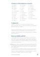
Countries of intended use in the EU AT - Austria HU - Hungary PL - Poland BE - Belgium IS - Iceland PT - Portugal BG - Bulgaria IE - Ireland RO - Romania CY - Cyprus IT - Italy SK - Slovak Republic CZ - Czech Republic LV - Latvia SI - Slovenia DK - Denmark LI - Liechtenstein ES - Spain EE - Estonia LT - Lithuania SE - Sweden FI - Finland LU - Luxembourg CH - Switzerland FR - France MT - Malta TR - Turkey DE - Germany NL - Netherlands UK - United Kingdom GR - Greece NO - Norway
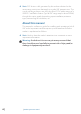
¼¼ Note: DSC distress calls generated by this radio are limited to the same range restrictions that apply to regular VHF transmissions. The vessel sending a distress can only rely upon DSC if within range of a GMDSS Coast Radio Station. Typical VHF range may be about 20NM, though this varies greatly depending upon installation, antenna type, meteorological conditions, etc. About this manual This manual is a reference guide for installing and operating a Link-6 VHF radio.
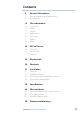
Contents 8 General Information 9 12 How to display and navigate menus Key functions 15 The radio menus 15 16 17 17 20 22 23 Scan menu Watch Display Radio setup DSC setup Alarms Reset 24 DSC call menu 24 26 27 DSC calls Track buddy Contacts 29 My channels 30 Shortcuts 31 Installation 31 32 32 36 Checklist Installation options Selecting a suitable mounting location First startup configuration 39 Specifications 42 Channel charts 42 50 52 EU and INTERNATIONAL channel chart USA channel c
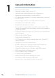
1 General Information • • • • • • • • • • • • • • • • • • • • • • 8| Your Link-6 provides the following useful features: Prominent channel display Adjustable contrast settings for the LCD Adjustable keypad backlighting for easy night-time use Waterproof and submersible to comply with IPx7 GPS latitude and longitude (LL) and time display (when connected to a GPS source) Choice of High (25 W) or Low (0.
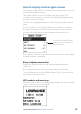
How to display and navigate menus The majority of the buttons, and both of the rotary knobs, can open menus with multiple options. The channel knob is used to scroll through the options. The currently selected option is indicated by a black highlight bar, and the text is inverted to white. Selection of a highlighted option is made by pressing the channel knob. If a list of options is too long for the page, a scroll bar is shown on the right side of the screen.
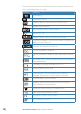
During normal operation, the following icons may be displayed on the screen depending on setup: Symbol Meaning Transmitting Transmition power Weather channel stored by user (EU/INT only) Weather alert enabled Receiver Busy with incoming signal Missed DSC call Duplex channel selected (off when Simplex) Local mode enabled (used when in areas of high radio traffic, ie inner harbour) Channel can only be received on DSC functionality is enabled DSC functionality is enabled, auto switching is turned off EU model
A typical display: 1. Channel is set to high power transmit 2. Missed call in the DSC call log 3. Channel is busy 4. Volume is under active control 5. Current channel saved in ‘My Channels’ 6. Track your buddy is enabled 7. Current channel will be skipped during a scan 8. Volume level indicator 9. Time (derived from GPS) - UTC offset is applied 10. Latitude/Longitude 11. Squelch level indicator 12. Channel number (2 or 4 digits) 13. The USA channel bank is active 14.
Key functions The following describes the direct functions of the keys/knobs. Where necessary, additional detail on any menus accessed by keys is covered in following chapters. 12 13 11 4 1 3 9 2 5 6 7 8 9 10 1. Channel knob / PUSH TO SELECT Turn knob for channel selection, menu scrolling, alphanumeric entry, and fine adjustment of backlight level (dependent on active menu). Short press to make selections in menus. Long press to open MY CHANNELS. 2. VOL / SQL Volume and Squelch level.
weather channel. 7. SCAN Short press to enter ALL SCAN mode. ALL SCAN sequentially scans all channels for activity. When a signal is received, scanning stops at that channel and the BUSY icon appears on the screen. If the signal ceases for more than 5 seconds, the scan automatically resumes. Turn the channel knob to temporarily skip over (lock out) a busy channel and resume the scan. The direction turned determines if the scan goes up or down the channel numbers (ie ‘forward’ or ‘reverse’).
11. H/L (handset mic only) Transmission Power. Press to toggle between high (25 W) or low (0.75W) transmission power for the entire channel bank. The HI or LO selection is shown on the LCD. Some channels allow only low power transmissions. Error beeps will sound if attempting to change the transmission power while on one of these channels. Some channels allow only low power transmissions initially, but can be overridden to high power by pressing (and holding) H/L after depressing PTT.
2 The radio menus A long press of the MENU button opens MENU SELECT page.
My channels Scan all channels selected in EDIT MY CHANNELS My channels + 16 Scans all channels selected in EDIT MY CHANNELS, while also checking the priority channel after every channel step. Edit my channels Allows creation of a custom list of channels - used in a MY CHANNELS scan. Watch This menu is for choosing a watch mode to enable, as well as selection of the watch channel.
Display This menu allows the user to partially customize the screen information displayed, and adjust the screen for best visibility to suit the user and operating conditions. Time display Select to switch the display of Time to ON or OFF. If turned ON, the display of COG/SOG is turned off, due to screen space constraints. LOC (Local Time) is displayed below the time if a UTC (Coordinated Universal Time) offset has been entered; otherwise UTC is shown in it’s place if no offset has been applied.
designed for use in areas of high radio noise; for example, close to a busy port or city. UIC Select between USA, International or Canadian channel banks. The selected channel bank is displayed on the LCD along with the last used channel. All the channel charts are shown in “Channel charts” on page 42. ¼¼ Note: UIC may not be available on all models. Power output Select to toggle between high (25 W) or low (0.75 W) transmission power for the entire channel bank. The HI or LO selection is shown on the LCD.
Ext speaker Select to switch the radio’s external speaker ON or OFF. Incoming voice calls and DSC alerts are prevented, but key beeps and alarms will still be audible. GPS MANUAL Select MANUAL to enter a GPS position (and time) from another source when radio is not receiving position data from an external antenna, or no antenna is connected. The manually entered GPS position can be used in DSC calls.
Time Format Select to toggle between 12 and 24 hour format. Vessel call sign Select to enter vessel callsign. Not used by radio - purely for record keeping purposes. Menu timeout An inactivity timeout can be set up to return the radio to normal operational mode when no activity is seen from the radio operator while radio is displaying a menu. Select between NONE, 5 MINS, 10 MINS, and 15 MINS. (default is 10 MINS). ¼¼ Note: A different timeout is used when the radio is left in a DSC call.
ATIS ID (EU ATIS radios only) Enter an ATIS number to access the radio’s ATIS functionality. This unique identifier must be supplied a local radio spectrum authority. DO NOT enter a random ‘made up’ number. ¼¼ Note: Contact a Lowrance dealer if you need to change your ATIS ID after initial input.
With AUTO SWITCH set to OFF, any channel change request will require manual confirmation. Test acknowledge (“TEST ACK”) The radio can be configured to automatically acknowledge an incoming test call, or require manual intervention: MANUAL Operator must manually choose to send acknowledgement, or cancel. AUTO The DSC test call is automatically acknowledged after a 10 second delay.
GPS alert function Turns ON or OFF all alerts for missing GPS data, including audible alarm, screen flash, and warning text. Alert volume Select between HIGH, LOW, and OFF. Screen flash Select between ON and OFF. WX alert (US/CAN models only) The WX alert is a warning to the user that a special weather station alert has been received. It comprises of an audible alarm and visual alarm; WX alert function Turns ON or OFF the radios response to weather alerts.
3 DSC call menu DSC (Digital Selective Calling) is a semi-automated method of establishing VHF, MF, and HF radio calls. One big advantage that DSC enabled radios offer is that they can receive calls from another DSC radio without being on the same channel as the calling radio. The calling radio will provide details on what channel to switch to so that voice communication can be established.
The Distress Call is automatically re-sent every 3.5 to 4.5 minutes until a distress acknowledgement is received.
All ships Used to place a call to ALL DSC equiped vessels in range, much like a distress call. The nature of the call must be selected, and can be either SAFETY or URGENCY. When the SEND TO page is displayed, turn the channel knob to select the channel to use for voice communication. Call logs Shows a record of SENT, RECEIVED, and DISTRESS calls. POS request Used to send a postion request to another vessel.
Select buddy Shows any existing ‘buddies’ already selected, and the option to add more. Selecting a ‘buddy’ already in the buddy list will remove them. Choose ADD/UPDATE BUDDY to view the full contacts list, and choose who to add for tracking. Start tracking / Stop tracking Selecting START TRACKING option initiates tracking of buddies in the Track buddy list that have been set to tracking ON. The radio will show a screen indicating which buddy is being called.
View/Add Contact Use this to store the names and associated MMSI’s of up to 50 vessels to be called regularly using DSC. Contacts are stored by name, in alphabetical order. Select ADD NEW to create a new contact. Selecting an existing name in the Contacts list gives the options to place a DSC call, make a position request, edit the contact, or delete the contact. View/Add Group Use this to create, edit, or delete up to 20 vessel groups, which are stored in alphanumeric order.
4 My channels The MY CHANNELS page is accessed by a long press of the channel knob. This page provides a shortcut to frequently accessed channels. The first time this page is opened, the entire channel list is shown so that the desired shortcut channels can be selected. Subsequent opening of this page will show a list of only the selected channels. Choosing one of the channel options immediately exits the page and sets the radio to that channel.
5 Shortcuts The Shortcuts page is accessed by a long press of the VOL/SQL knob. This page is provided as a shortcut to frequently accessed settings. The shortcut options available on this page are subject to selections made in ADD/EDIT SHORTCUTS. Add/Edit shortcuts Choose from the list of options which menu options should be added as shourtcuts; ¼¼ Note: The MY VHF page is only available to the operator when enabled as a shortcut - it can’t be accessed via another menu.
6 Installation This Lowrance DSC VHF radio is designed to generate a digital maritime distress call to facilitate search and rescue. To be effective as a safety device, this radio must be used only within the geographic range of a shore-based VHF marine Channel 70 distress and safety watch system. The geographic range may vary but under normal conditions is approximately 20 nautical miles. Checklist The following items should be supplied in the box.
Installation options • • There are two mounting options for the radio: Bracket mount: Using the supplied gimballing bracket the radio can be mounted to either sit on top of, or hang underneath any flat horizontal surface. The radio can be removed for storage and the viewing angle can be adjusted. Flush mount: The radio is recessed into a cavity, showing only the face of the radio. The radio fixture is permanent and the viewing angle cannot be adjusted.
Bracket installation The gimbal bracket provides an adjustable viewing angle with a 20º tilt range, so ensure the selected mounting location will provide the desired viewing and operating conditions: 1. Hold the bracket at the chosen location and use a soft pencil to mark the screw hole positions onto the mounting surface. 2. Use a 3mm (1/8” ) drill bit to drill the 4 pilot holes. 3. Using a Philips screwdriver, secure the bracket using the supplied 4x25mm self-tapping screws to the mounting location. 4.
Flush installation 1. Tape the installation template onto the chosen mounting location. 2. Cut out the area marked by the solid dark line (the dashed line indicates the total area that will be covered by the radio fascia after installation). 3. Use a 2.5mm (3/32” ) drill bit to drill the 4 pilot holes. 4. Remove the installation template. 5. Fit the gasket to the radio. 6. Slide the radio into the cavity. 7. Using a Philips screwdriver, secure the radio using the supplied 3.
Connect the radio wiring All wiring on the radio should be done with the vessel power supply turned off. While radio power is polarity protected, the fuse will blow if connection is made wrong way round. Ensure any unused bare wires are isolated from each other, to prevent the potential of a short circuit. ! Warning: never operate the radio without the antenna connected. This may damage the transmitter. The connectors are on the rear of the base unit, as follows: 12 34 56 7 8 9 10 + _ 1.
First startup configuration The first time the radio is powered up, the user is prompted to make a series of setting selections in order to allow the radio to perform to its full potential. Some steps must be completed; some are optional and can be completed later. The steps are outlined below for reference: Select the region and country the radio will be operated in. Enter MMSI number if known, or skip to next step. Re-enter number to confirm correct entry. ¼¼ Note: MMSI entry can only be done once.
Set the time offset for your region. Choose whether to display time in 12 or 24 hour. MMSI and ATIS ID • • • • • • • The MMSI is a unique 9 digit number and the ATIS ID is a 10 digit number. They are used on marine transceivers that have DSC (Digital Select Calling) functionality. An MMSI remains with a vessel, even if the vessel is sold on. An MMSI has 9 numeric digits (xxxxxxxxx). Your MMSI must not commence with a ‘0’. A Group MMSI begins with ‘0’ followed by 8 numeric digits (0xxxxxxxx).
Where a VHF is required on the inland waterways of the signatory countries, this must be capable of ATIS transmissions, and have the feature activated. An ATIS number is required which is issued by Ofcom when you add one or more pieces of ATIS equipment to your Ship Radio Licence. If you don’t have a user MMSI or ATIS ID, contact the appropriate licensing authority in your country. If you’re unsure who to contact, consult your Lowrance dealer.
7 Specifications GENERAL Power supply: 12 V DC battery system Nominal operating voltage: +12 V DC Low battery alert: 10.5 V DC +/- 0.5 V Over voltage protection: > 15.8 V +/- 0.5 V Current drain (Transmit): ≤ 6 A @ 25 W / 1.5 A @ 0.75W (12 V DC) Current drain (Receive): Less than 450 mA in standby Replacement Fuse: 8 A, Glass type 3 AG; 32 mm (1.
Compass safe distance: 0.5 m (1.
RECEIVER 12dB SINAD sensitivity: 20db SINAD sensitivity: Adjacent CH selectivity: Spurious response: Intermodulation rejection: Residual noise level: Audio output power: 0.25 µV (distant) / 0.8 µV (local) 0.35 µV more than 70 db more than 70 db more than 68 db more than -40 db unsquelched 2 W (with 8 ohm at 10% distortion) 4 W (with 4 ohm external speaker ¼¼ Note: Specifications are subject to change without notice.
8 Channel charts The following channel charts are provided for reference only and may not be correct for all regions. It is the operators responsibility to ensure correct channels and frequencies are used for local regulations. EU and INTERNATIONAL channel chart The following is a table of transmiting frequencies in the VHF maritime mobile band. ¼¼ NOTE: For assistance in understanding the Table, see Notes a) to zz) below.
Channel designator 01 02 03 04 05 Transmitting frequencies (MHz) From ship From coast stations stations 156.050 160.650 156.100 160.700 156.150 160.750 156.200 160.800 156.250 160.850 D D D D D 06 07 08 09 10 11 12 156.300 156.350 156.400 156.450 156.500 156.550 156.600 156.300 160.950 156.400 156.450 156.500 156.550 156.600 S D S S S S S 13 14 156.650 156.700 156.650 156.700 S S 15 16 17 18 19 20 21 22 23 24 156.750 156.800 156.850 156.900 156.950 157.000 157.050 157.100 157.150 157.200 156.
69 71 72 73 74 75 76 77 78 79 80 81 82 83 84 156.475 156.575 156.625 156.675 156.725 156.775 156.825 156.875 156.925 156.975 157.025 157.075 157.125 157.175 157.225 156.475 156.575 156.625 156.675 156.725 156.775 156.825 156.875 161.525 161.575 161.625 161.675 161.725 161.775 161.825 S S S S S S S S D D D D D D D PORT OPS PORT OPS SHIP-SHIP PORT OPS PORT OPS PORT OPS SHIP-SHIP SHIP-SHIP SHIP-SHORE PORT OPS PORT OPS TELEPHONE TELEPHONE TELEPHONE TELEPHONE 85 157.275 161.875 D TELEPHONE 86 157.
b) c) d) e) public correspondence shall be subject to prior agreement between interested and affected administrations. The channels of the present Appendix, with the exception of channels 06, 13, 15, 16, 17, 70, 75 and 76, may also be used for high-speed data and facsimile transmissions,subject to special arrangement between interested and affected administrations.
pollution operations in local areas, under the conditions specified in Nos. 51.69, 51.73, 51.74, 51.75, 51.76, 51.77 and 51.78. i) The preferred first three frequencies for the purpose indicated in Note a) are 156.450 MHz (channel 09), 156.625 MHz (channel 72) and 156.675 MHz (channel73). j) Channel 70 is to be used exclusively for digital selective calling for distress, safety and calling.
r) In the maritime mobile service, this frequency is reserved for experimental use for future applications or systems (e.g. new AIS applications, man over board systems,etc.).If authorized by administrations for experimental use, the operation shall not cause harmful interference to, or claim protection from, stations operating in the fixed and mobile services.
y) z) AAA) mm) w1) 48 | and Zimbabwe, the frequency bands 157.125-157.325 and 161.725161.925 MHz (corresponding to channels: 82, 23, 83, 24, 84, 25, 85, 26 and 86) are designated for digitally modulated emissions. From 1 January 2017, in China, the frequency bands 157.150 157.325 and 161.750 - 161.925 MHz (corresponding to channels: 23, 83, 24, 84, 25, 85, 26 and 86) are designated for digitally modulated emissions.
in the most recent version of Recommendation ITU-R M.1842 using multiple 25 kHz contiguous channels. From 1 January 2017, the frequency bands 157.150-157.175 MHz and 161.750-161.775 MHz (corresponding to channels: 23 and 83) are identified for utilization of the digital systems described in the most recent version of Recommendation ITU-R M.1842 using two 25 kHz contiguous channels. From 1 January 2017, the frequencies 157.125 MHz and 161.
USA channel chart Channel designator 6 8 9 10 11 12 13 14 15 16 17 20 24 25 26 27 28 67 68 69 71 72 73 74 75 76 77 84 85 86 87 88 1001 1005 1007 1018 1019 1020 1021 1022 1023 50 | Transmitting frequencies (MHz) From ship From coast stations stations 156.300 156.300 156.400 156.400 156.450 156.450 156.500 156.500 156.550 156.550 156.600 156.600 156.650 156.650 156.700 156.700 -156.750 156.800 156.800 156.850 156.850 157.000 161.600 157.200 161.800 157.250 161.850 157.300 161.900 157.350 161.950 157.
1063 1065 1066 1078 1079 1080 1081 1082 1083 156.175 156.275 156.325 156.925 156.975 157.025 157.075 157.125 157.175 156.175 156.275 156.325 156.925 156.975 157.025 157.075 157.125 157.175 S S S S S S S S S PORT OPS/VTS PORT OPS PORT OPS SHIP-SHIP COMMERCIAL COMMERCIAL RESTRICTED RESTRICTED RESTRICTED Note: Channel 70 is used exclusively for DSC and is not available for regular voice communications Channel 70 frequency:156.
CANADA channel chart Channel designator 1 2 3 4 5 6 7 8 9 10 11 12 13 14 15 16 17 18 19 20 21 22 23 24 25 26 27 28 60 61 62 63 64 65 66 67 68 69 71 72 73 52 | Transmitting frequencies (MHz) From ship From coast stations stations 156.050 160.650 156.100 160.700 156.150 160.750 156.200 160.800 156.250 160.850 156.300 156.300 156.350 160.950 156.400 156.400 156.450 156.450 156.500 156.500 156.550 156.550 156.600 156.600 156.650 156.650 156.700 156.700 156.750 156.750 156.800 156.800 156.850 156.850 156.
74 75 76 77 78 79 80 81 82 83 84 85 86 87 88 1001 1005 1007 1018 1019 1020 1021 1022 1024 1025 1026 1027 1061 1062 1063 1064 1065 1066 1078 1079 1080 1083 1084 1085 1086 2019 2020 2023 2026 2078 156.725 156.775 156.825 156.875 156.925 156.975 157.025 157.075 157.125 157.175 157.225 157.275 157.325 157.375 157.425 156.050 156.250 156.350 156.900 156.950 157.000 157.050 157.100 157.200 157.250 157.300 157.350 156.075 156.125 156.175 156.225 156.275 156.325 156.925 156.975 157.025 157.175 157.225 157.275 157.
2079 2086 --- 161.575 161.925 R R PORT OPS PORT OPS RX ONLY RX ONLY Note: Channel 70 is used exclusively for DSC and is not available for regular voice communications Channel 70 frequency:156.525MHz Canada weather channels Channel designator WX1 WX2 WX3 54 | Transmitting frequencies (MHz) From ship From coast stations stations -162.550 -162.400 -162.
60 mm (2.36”) 123.4 mm (4.86”) 166.7 mm (6.56”) Dimensional drawings | Link-6 operator manual 114.2 mm (4.5”) 161.4 mm (6.35”) 89.2 mm (3.
*988-11181-003*