
Datasheet


© Freudenberg Simrit GmbH & Co. KG | Technical Manual 2007554
Technical Principles | O-Rings and Static Seals
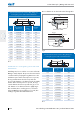
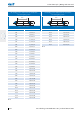
Groove dimensions for an ISC O-Ring fitting in a
rectangular groove with radial deformation
d
2
d
1
Ø
d
2
Seal surface
distance t
Groove
width
b
1
+ 0,2
Chamfer
15° Z
9,50 7,5 ±0,38 12,20 9,6
10,00 7,9 ±0,40 12,80 10,1
10,50 8,2 ±0,42 13,60 11,0
11,00 8,6 ±0,43 14,10 11,3
11,50 9,0 ±0,46 14,70 11,8
12,00 9,4 ±0,48 15,50 12,4
12,50 9,8 ±0,50 16,10 12,8
13,00 10,2 ±0,52 16,70 13,3
13,50 10,6 ±0,54 17,30 13,8
14,00 11,0 ±0,56 17,90 14,2
14,50 11,4 ±0,58 18,50 14,7
15,00 11,8 ±0,60 19,10 15,1
Tbl. 2
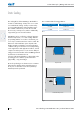
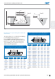
Installation in a rectangular groove with axial
deformation
With flange and cover seals the cross-section of the ISC
O-Ring is axially shaped. The pressure direction must be
considered when specifying the ring dimensions or the
installation space. Where external pressure is present,
the ring inside diameter should correspond to the
groove inside diameter or be dimensioned to be slightly
smaller. Where internal pressure is present, the ring
outside diameter should correspond to the groove out-
side diameter or be dimensioned to be slightly larger.
This avoid that, due to swelling pressure, movement
of the ISC O-Ring in the mounting groove results, thus
leading to a greater deformation and wear.
Groove dimensions can be found in the following table.
p
p
h
h
b
4
+
0
,
2
b
4
+
0
,
2
d
8
h
1
1
Ø
d
7
H
1
1
Ø
d
7
Ø
d
8
Ø
Pressure from outside
Pressure from inside
Fig. 4
Groove dimensions for an ISC O-Ring fitting in a
rectangular groove with axial deformation
d
2
d
1
Ø
d
2
Groove depth
h
Groove width
b
4
+ 0,2
1,50 1,10 ±0,03 2,20
1,60 1,20 ±0,03 2,20
1,78 1,40 ±0,04 2,40
1,80 1,40 ±0,04 2,40
2,00 1,50 ±0,04 2,80
2,40 1,80 ±0,05 3,30
2,50 1,90 ±0,05 3,40
2,62 2,00 ±0,05 3,50
2,65 2,00 ±0,05 3,60
3,00 2,30 ±0,06 4,00
3,50 2,70 ±0,07 4,60
3,53 2,70 ±0,07 4,60
Tbl. 3