
Datasheet


© Freudenberg Simrit GmbH & Co. KG | Technical Manual 2007 555
Technical Principles | O-Rings and Static Seals
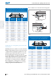
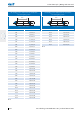
Groove dimensions for an ISC O-Ring fitting in a
rectangular groove with axial deformation
d
2
d
1
Ø
d
2
Groove depth
h
Groove width
b
4
+ 0,2
3,55 2,70 ±0,07 4,60
4,00 3,10 ±0,08 5,20
4,50 3,50 ±0,09 5,80
5,00 3,90 ±0,10 6,40
5,30 4,10 ±0,11 6,80
5,33 4,10 ±0,11 7,00
5,50 4,30 ±0,11 7,00
5,70 4,40 ±0,11 7,40
6,00 4,70 ±0,12 7,60
6,50 5,10 ±0,13 8,20
6,99 5,50 ±0,14 8,80
7,00 5,50 ±0,14 8,80
7,50 5,90 ±0,15 9,40
8,00 6,30 ±0,16 10,00
8,40 6,97 ±0,10 10,78
8,50 6,70 ±0,17 10,70
9,00 7,10 ±0,18 11,30
9,50 7,50 ±0,19 11,80
10,00 7,90 ±0,20 12,40
10,50 8,20 ±0,21 13,30
11,00 9,13 ±0,10 14,08
11,50 9,55 ±0,10 14,69
12,00 9,40 ±0,24 15,10
12,50 10,38 ±0,10 15,92
13,00 10,20 ±0,26 16,20
13,50 11,21 ±0,10 17,15
14,00 11,62 ±0,10 17,77
14,50 12,04 ±0,10 18,38
15,00 11,80 ±0,30 18,60
Tbl. 3
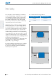
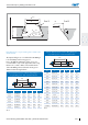
Installation in a triangular groove
Mounting spaces with a triangular form are sometimes
used with threaded flanges and covers.
It is, however, difficult to manufacture them with exact
dimensions.
As the sealing function of the ISC O-Ring depends on
the exact design of the mounting groove, it is impera-
tive that the dimensions and tolerances stated in the
following table be adhered to. Fitting into a rectangular
groove is preferred, however.
T
45°
f
7
H
8
Ø
Fig. 5
ISC O-Ring groove dimensions for installation
in a triangular groove
d
2
d
1
Ø
Groove dimensions
d
2
T
1,00 1,40 ±0,04
1,50 2,10 ±0,06
1,60 2,30 ±0,06
1,78 2,50 ±0,07
1,80 2,60 ±0,07
2,00 2,90 ±0,08
2,40 3,50 ±0,10
2,50 3,60 ±0,10
Tbl. 4