
Datasheet


© Freudenberg Simrit GmbH & Co. KG | Technical Manual 2007 553
Technical Principles | O-Rings and Static Seals
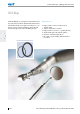
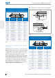
Installation in a rectangular groove with
radial change of shape
For the sealing of mortices, sockets, bolts or covers with
centering shoulders, ISC O-Rings are usually installed
as in the figure below.
The cross-section of the ISC O-Ring (d2) is radially
deformed upon installation. Whether the mounting
groove is cut into the inner or outer part depends on
the processing and installation possibilities.
t
t
g
Z
Z
g
r
2
r
2
r
1
r
1
b
1
+
0
,
2
b
1
+
0
,
2
d
3
h
9
Ø
d
6
H
9
Ø
d
9
f
7
Ø
d
5
f
7
Ø
d
4
H
8
Ø
d
1
0
H
8
Ø
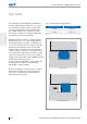
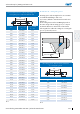
Fig. 2
With cover seals in hydraulic cylinders, installation as
in (→ Fig. 3) is to be preferred in order that no gap
enlargements occur on the non-pressurised side during
the elastic expansion of the hydraulic lines under
pressure load.
p
t
r
2
r
1
b
1
+
0
,
2
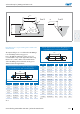
Fig. 3
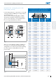
Groove dimensions for an ISC O-Ring fitting in a
rectangular groove with radial deformation
d
2
d
1
Ø
d
2
Seal surface
distance t
Groove
width
b
1
+ 0,2
Chamfer
15° Z
1,50 1,1 ±0,06 2,20 2,1
1,60 1,2 ±0,06 2,30 2,1
1,78 1,4 ±0,07 2,40 2,1
1,80 1,4 ±0,07 2,50 2,1
2,00 1,5 ±0,08 2,80 2,6
2,40 1,8 ±0,10 3,40 3,0
2,50 1,9 ±0,10 3,40 3,0
2,62 2,0 ±0,10 3,60 3,1
2,65 2,0 ±0,11 3,70 3,2
3,00 2,3 ±0,12 4,10 3,5
3,50 2,7 ±0,14 4,70 3,9
3,53 2,7 ±0,14 4,80 4,0
3,55 2,7 ±0,14 4,80 4,0
4,00 3,1 ±0,16 5,40 4,5
4,50 3,5 ±0,18 6,00 4,9
5,00 3,9 ±0,20 6,60 5,4
5,30 4,1 ±0,21 7,00 5,8
5,33 4,1 ±0,21 7,10 6,0
5,50 4,3 ±0,22 7,20 5,9
5,70 4,4 ±0,23 7,60 6,3
6,00 4,7 ±0,24 7,80 6,4
6,50 5,1 ±0,26 8,40 6,8
6,99 5,5 ±0,28 9,00 7,2
7,00 5,5 ±0,28 9,00 7,3
7,50 5,9 ±0,30 9,70 7,7
8,00 6,3 ±0,32 10,30 8,2
8,40 6,4 ±0,32 10,40 8,3
8,50 6,7 ±0,34 10,90 8,7
9,00 7,1 ±0,36 11,60 9,2
Tbl. 2