
Datasheet


© Freudenberg Simrit GmbH & Co. KG | Technical Manual 2007 557
Technical Principles | O-Rings and Static Seals
m
M
25 ±1 °
R
2
M
±
0
,
0
5
m
±
0
,
0
5
R
m
a
x
1
6
R
m
a
x
1
6
R
1
T
Detail X Detail X
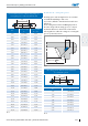
Fig. 6
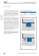
Installation in a trapezoidal groove with axial
deformation
The trapezoidal groove is used when the ISC O-Ring is
to be held firmly in the housing groove.
Due to the difficult manufacture of the groove, it is
recommended to only use this application with a ring
thickness of 3,5 mm or thicker. The inside diameter
of the ISC O-Ring is derived from the mean groove
diameter minus the ring thickness.
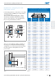
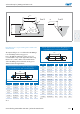
Groove dimensions for an ISC O-Ring fitting in a
trapezoidal groove with axial deformation
d
2
d
1
Ø
Groove dimensions
d
2
TmMR
1
R
2
3,53 2,9 ±0,07 2,9 3,1 0,6 0,2
3,55 2,9 ±0,07 2,9 3,1 0,6 0,2
4,00 3,3 ±0,08 3,3 3,5 0,7 0,2
4,50 3,7 ±0,09 3,7 4,0 0,7 0,3
5,00 4,1 ±0,10 4,1 4,4 0,8 0,3
5,30 4,4 ±0,11 4,4 4,7 0,9 0,3
Tbl. 5
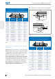
Groove dimensions for an ISC O-Ring fitting in a
trapezoidal groove with axial deformation
d
2
d
1
Ø
Groove dimensions
d
2
TmMR
1
R
2
5,33 4,4 ±0,11 4,4 4,7 0,9 0,3
5,50 4,5 ±0,11 4,5 4,8 0,9 0,3
5,70 4,7 ±0,11 4,7 5,0 0,9 0,3
6,00 5,0 ±0,12 5,0 5,5 1,0 0,4
6,50 5,4 ±0,13 5,4 5,9 1,1 0,4
7,00 5,8 ±0,14 5,8 6,3 1,2 0,4
7,50 6,2 ±0,15 6,2 6,7 1,2 0,4
8,00 6,7 ±0,16 6,7 7,3 1,3 0,5
8,40 7,25 7,3 7,9 1,5 0,5
8,50 7,1 ±0,17 7,1 7,7 1,4 0,5
9,00 7,5 ±0,18 7,5 8,1 1,5 0,5
9,50 7,9 ±0,19 7,9 8,6 1,6 0,6
10,00 8,3 ±0,20 8,3 9,0 1,7 0,6
Tbl. 5