
Installation Guide
Button Head Screw
Self Tapping Screws
2 ½” Zinc Plated Self Tapping Screw
OPEN POSITION
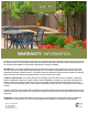
dual latch assembly
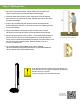
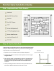
Step #3: Gate Hardware Installation (continued)
SPECIFICATIONS:
post dual latch
assembly
- PATENTS PENDING
To see a video about
gate hardware
installation, scan the
QR code.
2 ½” Zinc Plated Self Tapping Screw
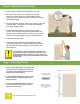
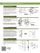
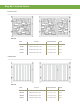
This latch is made for a single gate installation.
The triangular metal piece (C) is optional if the
gate needs to be locked from the inside.
The paddle (A) can be reversed by removing
the spring and the bolt holding the paddle to the
rectangular piece (B).
A
B
D
(The Paddle)
(Rectangular Piece)
(The Short Paddle)
C
(Triangular Piece)
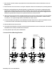
This double latch consists of the rectangular piece
(B) and a shorter paddle (D).
This can be achieved by removing paddle (A) and
replacing it with paddle (D).
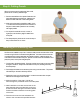
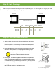
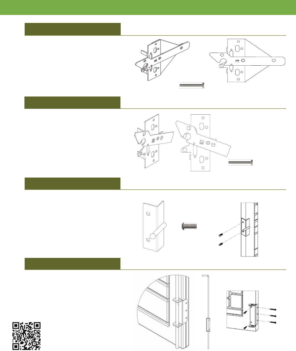
On a double drive gate, the latch should be
attached to one gate and the striker rod to the
other, using the button head screws for both.
First, identify the swing position gate. The swing
position gate will be the gate that is most
commonly used as a walk-access when only
opening one of the two gates. This gate will have
the striker rod attached to it. Using two supplied
button head bolts, attach the striker rod to the
swing position gate through the oval slots in the
striker rod (see illustration E). Tighten the button
head screws by using an Allen wrench.
Use the self-tapping screws and the supplied
bracket to fasten the drop rod to the bottom corner
of the gate. Roll pins may be removed and
re-inserted in order to thread the drop rod into the
bracket
Drop Rod
Striker Rod
Latch for Double Drive Gates
Latch for Single Gates
E
(Swing Gate)
B
(Rectangular Piece)