SERVICE MANUAL KING SERIES ASH-09AK, ASH-13AK
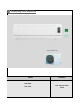
1 Summary and features 09/13 Outdoor unit: Model ASH-09AK ASH-13AK Remarks 1Ph 220~240V 50Hz R410a
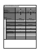
2 Technical specifications Model ASH-09AK COOLING Function Rated Voltage ASH-13AK COOLING HEATING 220-240V 220-240V 50Hz 50Hz Rated Frequency Total Capacity (W/Btu/h) HEATING 2650 /9050 2850/ 9730 3516/12000 4015/13700 Power Input (W) 820 785 1080 1104 Rated Input (W) 1110 1150 1500 1500 Rated Current (A) 5.69 5.9 7.6 7.6 Air Flow Volume (m3/h) (H/M/L)** Dehumidifying Volume (l/h) EER / C.O.
Model of Outdoor Unit Compressor Manufacturer/trademark Compressor Model Compressor Type L.R.A.
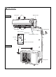
3 Part name Indoor unit Front Panel Filter Guide louver Air in Manual switch Air out Heat Cooling LED displayer Wall Pipe Wrapping Tape LED displayer Wireless remote control Set Temp DRY Run Remote control window Outdoor unit Connection pipe Air in Drainage hose Air out
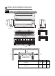
4 Outline and installation dimension Outline and installation dimensions of indoor unit H Air inlet D W Tube exit Wall-Mounting Plate: ASH-09AK ASH-13AK Rear View Ceiling Left Right Wall-Mounting Plate Model W(㎜) H(㎜) D(㎜) ASH-09AK 740 250 180 ASH-13AK 805 280 215
Outline and installation dimensions of outdoor unit ASH-09AK, ASH-13AK Unit:mm over over over over Bolt Nut Wrench
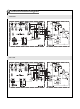
5 Electrical circuit diagram ASH-09AK ASH-13AK
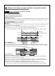
6 Manual of functions of remote controller and operation method Manual 1 of functions of remote controller 6.1.1 Temperature parameter The room setting temperature(Tpreset) The room ambient temperature (Tamb) 6.1.2Basic Functions Once energized, the compressor should in no way be restarted unless after 3-minute time interval at least. For the first energization, the compressor will be started without 3-minute lag.
Tpreset +2℃ Cooling Tamb Dry Tpreset -2℃ 6 min. Stop 6 min. 4 min. 4 min. Compressor Outdoor fan Indoor fan low speed Stop Run 6.1.2.2.3 Protection Antifreeze Protection Upon meeting the cooling condition, if it is detected that the system is under antifreeze protection, the compressor and outdoor fan will be stopped,and the indoor fan will run at low speed.
3.Other controls 1. Memory function Memory contents: Mode, up and down swing, Light, Setting temp., Setting fan speed, Ordinary setting Fahrenheit/Centigrade, after powered off, and powered on, it will run at the memory contents. If no timer setting function in last remote control order, the system will memorize the last remote control order, the system will memorize the last remote control order and work with last remote control setting.
(6) Turbo function The turbo function is available in Cool and Heat modes. (7) Dry function Dry function is available in Cool and Dehumidifying modes. (8) Auto fan speed control In this mode, indoor fan can run with Hig, Mid, Low speeds.
Manual 2 of functions of remote controller This manual is applicable to 18K, 24K models, the centigrade is used for the following function manual, if there will be the Fahrenheit degree, that will be TF= TCX1.8+32. 1.
DRY Modes When Tamb. Tpreset 2 , the unit will run under DRY cooling mode, in which case the compressor and outdoor fan will be started and the indoor fan will run at low speed. When Tpreset 2 Tamb. Tpreset 2 , the unit will run under Dry mode, in which case the indoor fan will keep run at low speed, the compressor and outdoor fan will be stopped after 6mins. After 4 minutes, the compressor and outdoor fan will be restarted. The dehumidifying process is so repeated in cycle. When Tamb.
If it is detected that the evaporator tube temperature is too high, the outdoor fan will be stopped. When the tube temperature resumes to normal,the outdoor fan will be restarted. Noise Silencing Protection If the unit is stopped by pressing ON/OFF, the reversal valve will be stopped after 2-minute l ag; or 2 minutes wi l l be delayed upon mode switching. Over current product The overcurrent protection is the same with the the over current protection under cool mode.
1hr. 2hrs. 2hrs. above Tpreset Tpreset Tpreset temp. Tpreset Turbo function The turbo function is available in Cool and Heat modes. Dry function Dry function is available in Cool and Dehumidifying modes. Auto fan speed control In this mode, indoor fan can run with Hig, Mid, Low speeds.
7 Dissassembly Procedures (09) Disassembly procedures for indoor unit Operating Procedures / Photos 1. Disassemble the front panel, filter Push the rotating shaft of front panel outsidely to put out it from the groove, screw off one screw on the display guard board, then take down the displayer connection wire, can take down the front panel. Front Pane Screw Filter 2. Disassemble the guide louver Bend the guide louver so that the movable lock of guide louver is released to remove the guide louver.
Operating Procedures / Photos 4. Disassemble the electric cover Screw off the screw, then press the clasps in by Screw till they loose, then lift up wards the electric cover. Electric cover 5. Disassemble the electric box Clasp Grounding wire Screw off the grounding wire of the evaporator, remove the temperature sensor for the pipe, put Tube Sensor out the connection lines for the step motor and the indoor motor. Screw off the screw fixing the electric box. Remove the electric box. Screw 5.
Operating Procedures / Photos 6. Disassembling the evaporator Screw off one screw which fix the connection pipe clamp. Take off the connection pipe clamp. Screw CAUTION: When repair, Carefully take out the evaporator and pay attention to protect the connecting pipe. Screws 7. Disassembling motor and cross flow fan Screw off 4 screws fixing the motor cover and then take the motor cover out.
(12) Disassembly procedures for indoor unit Operating Procedures / Photos 1. Disassemble the front panel, filter Open the front panel ,Push the filter upwards to unloose the clasp, and then pull out the two filters. Front Pane Screw off one screw on the displayer box, take down the guard board then disconnect the displayer connection wire, can take down the front panel. Display Cover Screw Filter 2.
Operating Procedures / Photos 4. Disassemble the electric cover Press the clasps in by till they loose, then lift up wards the electric cover. Electric cover 5. Disassemble the electric box Screw off the grounding wire of the evaporator, remove the tube sensor and temp sensor support, Temp Sensor Support Grounding wire Tube Sensor put out the connection lines for the step motor and the indoor motor. Screw off the screws fixing the electric box. Remove the electric box. Connector 5.
Operating Procedures / Photos 6. Disassembling the evaporator Screw off 4 screws fixing the left and right side of the evaporator, then elevate left side the evaporator to remove it backward. CAUTION: When repair, Carefully take out the evaporator and pay attention to protect the connecting pipe. Screws 7. Disassembling motor and cross flow fan Motor Press Plate Screw off 4 screws fixing the motor cover and then take the motor cover out.
(Conventional 09) Disassembly procedures for indoor unit Operating Procedures / Photos 1. Disassemble the front panel, filter Push the rotating shaft of front panel outwards to unloose the clasp, and then pull out the front panel. Front Panel Electric Box Cover Screw off the screws of the electric box cover, and take down the electric box cover. Filter 2. Disassemble the guide louver Bend the guide louver so that the movable lock of guide louver is released to remove the guide louver.
Operating Procedures / Photos 4. Disassemble the electric box cover Screw off the screw, then press the clasps in by till they loose, then lift up wards the electric cover and the light board. Light Board Screw Electric box cover 5. Disassemble water tray Loosen up the clasp at the front of and the rear of water tray sub-assy and lift them up, can take out the water tray sub-assy.
Operating Procedures / Photos 7. Disassembling the evaporator Screw Screw off 1 pc screw fixing the connecting pipe clamp, take down the connecting pipe clamp. CAUTION: When repair, Carefully take out the evaporator and pay attention to protect the connecting pipe. Screws 8. Disassembling motor and cross flow fan Screw off 4 screws fixing the motor cover and then take the motor cover out.
(Conventional 12) Disassembly procedures for indoor unit Operating Procedures / Photos 1. Disassemble the front panel, filter Push the rotating shaft of front panel outwardly, Front Panel to make it out of the groove, then can take down the front panel. Filter 2. Disassemble the guide louver Bend the guide louver so that the movable lock of guide louver is released to remove the guide louver. Guide louver 3. Disassemble the front case Open the 2 screw covers at the front case and screw off 1 screws.
Operating Procedures / Photos 4. Disassemble the Light Board and electric cover Screw off 1pc screw of light board, then can take down the light board. Light Board Electric cover 5. Disassemble the electric box Lossen the grounding wire of the evaporator, remove the tube sensor and temp sensor support, Grounding wire put out the connection lines for the step motor and the indoor motor. Screw off the screws fixing Temp Sensor Support Tube Sensor the electric box. Remove the electric box. 6.
Operating Procedures / Photos 7. Disassembling the evaporator Screw off 4 screws fixing the left and right side of the evaporator, then elevate left side the evaporator to remove it backward. CAUTION: When repair, Carefully take out the evaporator and pay attention to protect the connecting pipe. Screws 8. Disassembling motor and cross flow fan Motor Press Plate Screw off 4 screws fixing the motor cover and then take the motor cover out.
(09/12) Disassembly Procedures for Outdoor Unit Operating Procedures / Photos 1. Disassemble Big Handle Unscrew the screw fixing the big handle,and then remove it downwards to take it out. Screw 2. Disassemble Top Cover Unscrew the 2 screws fixing left side of top cover and the 1 screw fixing the right side to remove the top cover. Screws 3. Disassemble Rear Grill Unscrew the 4 screws fixing the rear grill to remove it.
Operating Procedures / Photos 4. Disassemble Front Panel Unscrew the 5 screws fixing the panel and dextrorotate the front panel to pull it out from groove. Screws 5. Disassemble Right Side Plate Unscrew the 2 screws fixing electric box ,and then unscrew the 5 screws fixing the right side plate to remove it. Screws Right Side Plate Screws 6.
Operating Procedures / Photos 7. Disassemble Axial Flow Fan Loosen the fastening nut fixing the axial flow fan with a spanner, and then take out the nut, spring Axial Flow Fan gasket and flap gasket in turn. Nut 8. Disassemble Motor and Motor Support Unscrew the 4 screws fixing the motor to take out the motor,and then unscrew the 2 screws fixing the motor support to take it out. Screws Motor Screws 9.
Operating Procedures / Photos 10. Disassemble Capillary Respectively unsolder the weld spots of main capillary and auxiliary capillary to take off the capillary. Capillary 11. Disassemble Gas and Liquid Valves Unscrew the two bolts fixing gas valve and liquid valve.Unsolder weld spots between gas valve and and air-return pipe to remove the gas valve. Unscrew the two bolts fixing liquid valve. Unsolder weld spots between liquid valve and capillary to remove the liquid valve.
9 Failure and analysis Note: When replacing the controller, make sure insert the wire jumper into the new controller, otherwise, the running indicator off 3s, blink 15 times, (the dual eight will display C5) but cannot turn on the unit. The breaker trips at once when it Measure insulation resistance to ground to see if there is any leakage. is set to "ON". Trip of breaker or blow of fuse The circuit or the part of the air conditioner has malfunction.
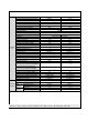
Improper set of temperature Adjust set temperature If cooling (heating) load is proper Check the forecasted load of cooling (heating) The refrigerant has leakage or is insufficient Malfunction of refrigerant flow Leakage between the high pressure and the low pressure inside the compressor Malfunction of four-way valve Poor COOL(HEAT) operation Local block of capillary Blockage of cooling system Heat insulation for the connection pipes of the indoor unit and the outdoor unit is bad.
The indoor fan motor is burned or breaks or has the heat protector malfunction. The fan does not run when it is set to supply air. In the cooling and heating mode, the compressor runs, but the outdoor fan does not run. The compressor is too hot and leads to the action of the protector. The built-in heat protector of the motor breaks frequently because the motor is abnormal. Replace the fan motor Wrong connection Make the correction connection based on the circuit drawing.
Drainage pipe blocked or broken Change drainage pipe Water leakage Wrap of refrigerant pipe joint is not close enough. Re-wrap and make it tight. Fan of indoor unit contacts other parts. Adjust fan location. Foreign object in indoor unit Take out the foreign object. Compressor shakes too much. Abnormal sound and shake Adjust support washer of compressor, and tighten loosen screws. Touch of pipeline of outdoor unit Separate the touching pipeline. Touch of inner plates 1. Tighten connect screw.
PG motor locked protection H6: Probable reasons: 1. Air vents were blocked which may cause the fan speed is too slow; 2. Fan blade locked; 3. Motor locked; 4. Fan motor capacitor damaged; 5. Motor damaged (ordors, winding, open circuit or shortcircuit are not normal, when testing the winding, pls distinguish whether the motor body cause temperature is too high so that bring on the thermal protector starts up) 6.
PARTS GUIDE KING SERIES ASH-09AK, ASH-13AK
Contents 04..………………………………….......................................................ASH-09AK Indoor unit 06..…………………………………………………………………...…ASH-13AK Indoor unit 08..…………………………………………………………………....ASH-09AK Outdoor unit 10..………………………………………………………………........
Explosive view and spare parts list of indoor unit ASH-09AK
No.
Explosive view and spare parts list of indoor unit ASH-13AK
No.
Explosive view and spare parts list of outdoor unit ASH-09AK
No.
Explosive view and spare parts list of outdoor unit ASH-13AK
No.