OPERATING MANUAL AUTOMATIC PNEUMATIC MACHINE TO SET EYELETS (GROMMETS) AND WASHERS ImagePerfect MODEL: EP-300 WARNING: SPANDEX DECLINES ANY LIABILITY ABOUT THE INCORRECT USE OR MISUNDERSTUNDING ABOUT THIS OPERATING MANUAL.
INDEX 1 INTRODUCTION. ........................................................................................ 3 1.1 1.2 2 TECHNICAL DATA....................................................................................... 4 2.1 2.2 3 INSTALLATION POSITION REQUIREMENTS. ...........................................................6 PENUMATIC INSTALLATION.................................................................................6 TRANSPORT..........................................................
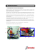
1 INTRODUCTION. 1.1 INTRODUCTION. This machine has been designed to set eyelets and washers, making in just one operation the feeding of the eyelet and washer, cutting and setting. This unit has been specially manufactured to set Image Perfect plastic eyelets. EP-300 has been designed to set eyelets on PVC banner materials, on fabrics might create wrinkles as it is not possible to make adjustments in the tooling. The standard eyelets holes are Ø8, Ø12 and Ø16 mm.
2 TECHNICAL DATA. 2.1 MACHINE SPECIFICATIONS AND OPERATION. EP-300 is mounted on a plastic (PE) table with four wheels on the corners and one in the center, all of them with breaking system. It has been designed to set fully automatic eyelets and washers, only eyelets or just to punch holes on the material.
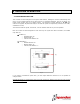
As seen on Fig. 1, eyelets are on the deposit (A) and washers on the deposit (C). Both deposits have 220 V motor. When turning, eyelets and washers come down through the raceways (B) and (D) towards the feeding area (G) where setting dies are located to make cutting and closing of the eyelet. 1. EP-300 is controlled by a PLC located inside the red cover of the machine.
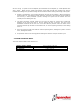
3 INSTALLATION. 3.1 INSTALLATION POSITION REQUIREMENTS. The minimum space recommended must be sufficient to keep that safety space in all directions for the operator to work properly. WARNINGS: Please note that that both the electrical wire and the air hosepipe should never be completely stretched. 3.2 PNEUMATIC INSTALLATION. The machine has an air inlet valve, type quick acting coupler (ISO 6150-B standard) ∅8 mm, located in the back of the machine (H). (H) Fig.
3.3 TRANSPORT. Always unload the crate with a forklift, securing the load with slings on the sides. To transport the machine to its permanent location, the following precautions should be taken in account: - Never stand beneath the wood crate. Use protective gloves. Avoid balancing the machine. Never overturned the machine. Lift or move the load gently. Do not make sudden movements. Always move the machine in vertical position.
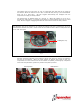
- The machine has an air inlet valve “H” (fig. 2) to manually open and close the air supply to the machine; When the machine is not in use, it should be shut (see fig. 3) to avoid accidents when use by a third party. We also suggest disconnecting the hosepipe from the compressor/air supply for safety reasons. - The machine has an ON/OFF switch (G), (see Fig. 1). When the machine is not in use, it should be on OFF position, (no lighting on the switch) to avoid accidents when use by a third party.
4 MACHINE OPERATION. 4.1 MACHINE DESCRIPTION. This machine has been designed to set eyelets with washers, feeding the machine automatically both parts, on PVC coated material and in general terms on plasticized materials, but not on fabrics as it might create wrinkles due to its setting system. The maximum cutting diameter is 16 mm (the machine is supplied, adjusted and ready to use with the eyelet size required by customer on its order, standard is 12 mm).
4.2 CHECKING THE MACHINE BEFORE STARTING. Before using the machine for the first time, or when the location of the machine is changed, or adjustments or part replacements are made, we advice customers to check that the machine has not suffered a blow or breakage. The main controls are on the right hand side of the machine: (K) (H) (G) (F) Fig.
4.3 EYELET SETTING. 1. Check that the air inlet valve “H” is on OPEN position (fig. 5). 2. Check that the main switch (G) is on ON position (with the green light on). 3. As soon as the machine is on position “ON”, the engines on both deposits will start to turnaround. The brushes push out the eyelets and washers filling the raceways. To extend the life of the engines, they will stop when operator is not using the machine for a period of 25 seconds.
5 ADJUSTMENTS. 5.1 WARNINGS ABOUT THE ADJUSTMENTS. The parts that should be replaced on a regular basis due to normal wear are the cutting or bottom die “M” and setting or top die “N”. We will see that the parts need to be replaced when either the cutting or the setting is not accurate. We always recommend having a spare set of these parts on your stock. (M) (N) Fig.
On the back of the machine are the electro valves (3) that distribute the compressed air to run the different operations needed to set the eyelets. The first one controls the main cylinder (that has the top die) and has an orange switch. On its back has a label “EV2” With one finger press the orange switch and do not remove it. The axle of the cylinder will descend. Without releasing the finger on the switch, shut off the air inlet valve so the axle of the cylinder stays on its lower position.
Remove the set screw from the top die. IT IS IMPORTANT NOT TO DAMAGE THE MACHINE THAT YOU REMOVE THE SCREW FROM THE DIE, NOT JUST LOOSEN IT. Remove the set screw from the bottom die. IT IS IMPORTANT NOT TO DAMAGE THE MACHINE THAT YOU REMOVE THE SCREW FROM THE DIE, NOT JUST LOOSEN IT. Open the air inlet valve so axle of the cylinder moves towards its upper position. Close the air inlet valve to access the setting area.
Remove top die form the axle of the cylinder. Remove bottom die. Place your fingers underneath the stainless steel plate and lift it gently. 1. 2. 3. Remove from the new die the set screws (top & bottom). Assemble new die putting both parts together. Check that the holes of the set screws are on the same side, as they have to be on the front of the machine. Install the new die with the holes for the set screws looking to the front of the machine.
With your hands out of the setting area: 1. 2. Open the air inlet valve. Press the switch of the first electro valve so axle of the cylinder descends. Without removing your finger from the first electro valve, close the air inlet valve. With an allen wrench, install back the set screw of the top die. With an allen wrench, install back the set screw of the bottom die.
Tighten the four screws of the safety protection. Open the air inlet valve and with your finger press the first switch of the electro valve to check that the top die fits well into the bottom one. Once we have finished these operations we will be ready to start making settings as usual.
6 MAINTENANCE. There is no need to lubricate any mechanical parts of the machine. For an optimum operation of the EP-300 it is important to have some parts clean, and this operation should always be done with a) the main air inlet valve on position “OFF” and b) the main switch on “OFF” position (no light on). The raceways where eyelets and washers come down should be always kept clean; we recommended doing it at the end of the day with compressed air.
7 FAILURES. 7.1 TROUBLESHOOTING. PROBLEM CAUSE SOLUTION 1. Check that the air hosepipe is connected to the compressor. 1. Connect the air hosepipe. 2. Check that the air inlet valve is on open position. 2. Open the air inlet valve. 3. Check that main switch of the machine is on position “ON” (with light). 4. Change the position to “ON”. 3. Check that the air pressure on the circuit is 6Kg/cm2. 3. Adjust the pressure gauge until the manometer has the correct pressure. 1.
8 SAFETY. 8.1 SAFETY DEVICES. The machine has a range of protection devices to prevent operator (except on maintenance or repairs) from accessing dangerous areas where can be injured. The dangerous part of the machine is the setting area “X”, where operator has the risk of crushing his fingers or hands. (K) (H) (G) Fig. 12 (F) (X) (L) Fig.
CLOSE position OPEN position Fig. 13 Fig. 14 ⇒ Main switch “G”: When set on “OFF” position (no light) will not set eyelets even if you press the setting button (F). ⇒ Emergency stop “K”: It will cut all power off when use by operator in case there is an emergency running the equipment.
9 ANNEX. 9.1 SPARE PART LISTIG. REFERENCE DESCRIPTION EP-300 Die 12mm EP-300 Safety protection EP-300 Brushes EP-300 Acrylic deposit cover 9.2 SUPPLIED TOOLING.
9.3 PNEUMATIC DRAWING.
9.4 ELECTRICAL DRAWING. 9.5 GUARANTIES. Model EP-300 has a guarantee period of 12 months since purchasing. Within this period, Spandex will replace free of charge all spare parts that under Spandex knowledge have manufacture defects The guarantee will not cover assemble / disassemble of the unit but will cover their freight cost. The guarantee will not cover those parts with normal wear for the machine use as the setting dies.