TURBO® STRIPPER II Operating Manual Read before use and keep safe Rev A Starting With Turbo II Ser# 193-07 06/21/07 (800) 624-2408 (530) 626-9386 Fax (530) 626-5144 6686 Merchandise Way Diamond Springs, Ca 95619 www.sineqco.
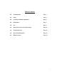
Table of Contents 1.0 Technical Data Page 3 2.0 Safety Page 3 3.0 Assembly & Handle Adjustment Page 6 4.0 Maintenance Page 7 5.0 Use Page 8 6.0 Information About Various Floorings Page 11 7.0 Trouble Shooting Page 11 8.0 Spare Parts/Schematics Page 15 9.
1.0 Technical data/technical description Power supply Power consumption Number of strokes Sound pressure level Sound energy level Hand/Arm-Vibration Weight 110-120V AC 2200W 5000 strokes/min 92 dB(A) 105 dB(A) 10 m/s2 350 lbs Comes with: Turbo® Stripper, 2 rigid blades, safety goggles and tool kit. 2.0 Safety The Sinclair Turbo® Stripper is state of the art designed and meets all standard safety requirements. 3.1 Safety Instructions Disconnect the power supply before any maintenance is carried out.
Transport Always remove the blade before transporting the machine. Disconnect the power supply and the plug of the clutch before removing the handle. Otherwise you might damage the hydraulics of the clutch. Mount the steel plate (1) instead of the clutch. Turn thumb screw (3) clockwise until the drive wheels are locked. This way the machine cannot move by itself. Never transport the machine without the wheels blocked. 2.
2.4 Restriction of use The Turbo® Stripper is exclusively for removing bonded floor covering in dry environments. It should not be used for any other purpose. Sinclair Equipment Company cannot be held responsible for any damage or loss caused by incorrect use. 2.5 Genuine Spare Parts Spare parts and accessories are manufactured uniquely for the Turbo® Stripper. It must be emphasized that parts obtained from unauthorized sources must not be used.
3.0 Assembly of Machine & Handle Insert handle into Turbo II base as shown in diagram. Tighten wing bolts in handle. Note that bolts are spring loaded to get past foot pad. Position both bolts facing up as shown in diagram. 3.1 Adjustement Of Handle To adjust handle, loosen wing bolt on back of handle. Pull knob on side lever and lift torwards you. Pull locking knob out from back of handle and slide handle up or down. Release spring loaded knob where needed & tighten wing bolt.
4.0 Maintenance The Turbo® Stripper is virtually maintenance free. The guide shaft castings require lubrication from time to time. (after approx. 1650 sq. feet). Initially the machine is fully lubricated and should not require any additional lubrication for the first 5000 square feet. The grease fittings are located on each side. (See Diagram 1) To Grease the gearbox on it’s right side, remove left wheel and bottom cover. Spin axel/gearbox to expose grease fitting.
Changing the blade Disconnect the power supply and put on the blade protection before changing the blade. Use work gloves for your own safety. - release bar on side of handle & tip the machine as shown - put on the blade protection - (enclosed in the tool set) Warning! Very sharp blade! You may cause injury without using the blade protection! - clean and loosen screws of the blade mounting Attention! Set the wrench at a position opposite to the blade to avoid injury.
The Turbo® Stripper is equipped with a Power -on indicator lamp (1) and an operating Switch located at the top of the handle. The switch has a restart protection for low-voltage failures. If the lamp does not indicate power-on, use another power socket or check power supply. Before starting work, cut the floor covering into strips of about 12 “. You cannot work faster if you cut wider strips. To begin, cut one strip crosswise. Then lift the flooring slightly in order to get the blade underneath it.
Assembly of support for additional weight (accessory) The weight of the Turbo Stripper is expandable by 1 up to 3 additional weights (each weight is 66 lbs) Sinclair part# T38535 Individual weight shifting is possible at 3 positions (see picture).
Emergency running The Turbo Stripper can be operated also with broken or damaged hand clutch as follows: - Disconnect power supply - Insert emergency-run-unit in place of clutch. - Screw-in thumb-screw (3) until the driving wheels are blocked - If the emergency-run-plate is mounted, the motor drive is always switched on. The machine starts running immediately after switching on. 6.
7.1 Repairing the Hydraulic System To repair the hydraulic system, use the Sinclair Hydraulic Clutch Repair Kit, which can be ordered through your local distributor. Hydraulic Clutch Repair Kit This kit contains all hydraulic fittings, compression washers, tubing, fluid, and specific tools necessary to completely rebuild the Turbo® Stripper’s hydraulic clutch assembly. Not included in the kit is a master cylinder and slave cylinder.
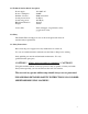
Filling and Bleeding The System Turn the clutch adjustment screw #2 (2mm Allen screw, located in the handle behind the lever of the master cylinder #7) counterclockwise as far as it will go. Insert the straight barbed adapter into the top end of the clear tubing and insert the tip of the syringe into the bottom end of the tube. Fully depress the syringe’s plunger to expel all air, dip it in the fluid and draw the plunger back slowly to fill the syringe at least half way.
Turbo Hydraulic Clutch Parts 1. Hydraulic Tubing – T099998T (Order qty 42) 2. Master Cylinder with Lever. (#2�)- T0730236 3. Screw for Clamp – T0999996 4. Clamp – T0999995 5. Lever Blade W Plunger & Lock – T0999994 6. Slave Cylinder – T0321830 7.
Spare Parts/Schematics Schematic # 1 4 5 6 8 12 13 14 15 16 19 20 21 22 23 24 25 26 27 28 29 30 31 32 33 34 35 36 37 38 39 41 42 44 45 46 47 48 49 52 53 54 57 58 59 61 62 63 64 Description Chassis Piston block Screw M 8x30 Washer, M8 Lubricating nipple Cover Screw M 8x25 Additional Weight Screw M10x80 Screw Nut Bushing 20x26x20 Blade holder Turbo / Jaw Striking foot Turbo Cyl.
65 66 67 68 69 70 71 72 73 75 76 77 78 79 80 81 82 83 84 85 86 87 88 89 90 91 92 94 95 96 97 98 99 100 101 102 103 104 105 106 107 108 109 110 113 114 115 116 117 118 122 123 125 Circlip I 62 Circlip A 17 Ball bearing 6305 Circlip A 30 Excenter shaft Turbo Nut key 4x4x20 Key 6x6x25 Circlip A 25 Bearing block right or left Screw M 10x70 Cyl.
126 128 129 131 132 133 136 137 138 139 140 141 142 146 147 148 149 150 151 176/177 178 179 180 181 Hydraulic-clutch assy Transport Axle Strain relief Handle Cyl. Screw, micro M6 x 20 Bracket for Lifting Strap Cyl. Screw, M8 x 16 Washer Indicator Cyl. Screw, M6 x 60 Fitting Elastic Stop Nut M8 Belt pulley Switch Top Hat Rail Cyl.
TURBO, EXTRO, SUPER, BRAVO, DURO & ECO STRIPPER SUGGESTED BLADE SELECTION BRAVO/DURO/ECO STRIPPER #10-4906 8”Rigid. Our standard blade for removal of vinyl, carpet, adhesive, etc. Bevel edge of blade should be up for concrete and down for wood sub-surfaces. Precutting of carpet and vinyl needed. #10-4904 8”Flexible. Same as above, yet for uneven concrete surfaces and some soft foam back carpet. #10-4907T 8”Tile Blade. For use on VAT and VCT tile. Prevents tile from jamming in between blade and blade holder.
STANDARD WARRANTY SINCLAIR EQUIPMENT COMPANY’S tools are warranted to be free of defects in workmanship and materials for a period of one year from the date of original purchase. Should any trouble develop during this one year period, return the complete tool, freight prepaid, to SINCLAIR’S authorized Service Center. If inspection shows the trouble is caused by defective workmanship or materials, SINCLAIR EQUIPMENT COMPANY will repair, or, at its option, replace without charge.
Notes 20