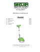
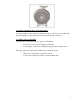
390 Surface Prep Machine Operating Manual October 31, 2005 Read before use and keep safe Table of Contents 1.0 2.0 3.0 4.0 5.0 6.0 7.0 Technical Data Safety Safety Instructions Maintenance Use Trouble Shooting Schematics Page 2 Page 2 Page 2 Page 4 Page 4 Page 6 Page 7 (800) 624-2408 (530) 626-9386 Fax (530) 626-5144 6686 Merchandise Way Diamond Springs, Ca 95619 www.sineqco.
1.0 Technical data/technical description Power supply Power consumption No-load speed Sound pressure level Sound energy level Hand/Arm-Vibration Weight 110V AC 1300W 154 / min. 54 dB(A) 67 dB(A) 4.5 m/s2 97 lbs. Includes: 390 Grinding Machine, Tool Kit, Operation Manual 2.0 Safety The Sinclair 390 Surface Prep is state of the art designed and meets all standard safety requirements. 3.0 Safety Instructions Disconnect the power supply before any maintenance is carried out.
.1 Introduction This operating manual should be used to get the most benefit from your 390 Surface Prep machine. Following these instructions will both extend the life of your machine and reduce repair costs. Please make sure you are fully familiar with the operating instructions before using this machine. 3.2 Danger while working with the machine The 390 Surface Prep is designed to the highest technical standards.
.0 Maintenance The 390 Surface Prep machine is virtually maintenance free. The roller bearing and gearbox need not to be lubricated. Mounting and changing the paper bags of the vacuum unit The vacuum unit can be used with paper bags or with the enclosed textile bag.
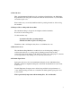
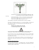
Assembly of mounting discs, pads and brushes Lay the machine down on the handle. Thus the support of the discs is accessible. Put the mounting disc on the actuation and lock it by turning anti-clockwise. Assembly of the vacuum unit Assemble the vacuum unit with two supports to the handle. - insert lower connector into the plastic mounting lock the upper connector by shifting the upper plastic mounting down The upper plastic mounting can be shifted by loosening the screws.
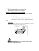
- Put the handle (2) in working position with the big, right lever (1). We recommend positioning the handgrip in the height of the - Lift the handle slightly, to make sure the machine stands horizontally. Move the left or right safety lock (3) located onto the grip inwards. Switch on the machine with the respective lever (4). user’s hip. After switching on the machine, the handle will move shortly to the right. The direction in which the machine moves, is controlled by lifting or lowering the grip.
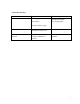
6.0 Trouble shooting Trouble Machine does not start Eventual Power supply disconnected Blown Fuse Elimination Have machine repaired by a qualified electrician, resp. change parts Defective cable or plug Switch-on lever cannot be actuated Assembly of handle wrong, described in section 5.
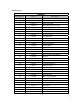
7.0 Schematics MACHINE Schematic # Part # Description 1 021625 Top Cover + Motor Housing 2 021626 Base Link 3 021627 Rubber Washer 4 021629 Fastening Screw for Gear 5 021628 Balancing Weight 6 021629 Fastening Screw for Weight 7 021630 Fastening Screw for Housing 8 017284 Screw 4.
HANDLE Schematic # Part # Description 1 015439 Screw 2 & 11 014193 Front & Rear Pistol Stock 3 015440 Adjusting Lever for Shaft 4 05441 5 014814 Screw Nut 6 015442 Lever for Water Supply 7 015443 Splint-Pin 8 015444 Spacer 9 015445 Lever for Left Switch 10 015446 Ball 10.
ELECTRICAL INSTALLATION Schematic # Part # Description 1 021637 3 05493 4 015514 Switch 5 018014 Screw for Fixed Link 6 018027 Screw for Cover 7 015496 Cable Clip 8 015497 Holding Device 9 015498 Protective Rubber Sleeve 10 021659 Cable + Connector Plug 11 021624 Cable Support 12 021623 Connecting Cable 15mm 13 018419 Screw Nut 14 033965 Spare Socket 15 015502 Socket 16 018332 Screw 17 021662 Socket Cover 18 015503 Starting Condensor 156MF 19 20 015504 01
GEAR Schematic # Part # Description 31 015507 Oil Seal Washer 32 033963 Top Cover 33 018422 O-Ring 34 018237 Washer 35 015489 Bearing E20 36 018424 Lay Shaft 37 018425 Bearing 16-004 38 018426 Bearing E15 39 015508 Gear Shaft 40 015509 Gear 41 018427 Gear Holder 42 018428 Bearing 16.
Vacuum Schematic# 1 2 3 4 5 6 7 8 Part# SP014038 SP014039 SP015352 SP015353 SP015354 SP015355 SP015356 SP037299 Description Tube with branch connection Extraction ring with brushes Branch connection Brushes Adapter Supporting cage Suction Case Paper Bags 5/pk
STANDARD WARRANTY SINCLAIR EQUIPMENT COMPANY’S tools are warranted to be free of defects in workmanship and materials for a period of one year from the date of original purchase. Should any trouble develop during this one year period, return the complete tool, freight prepaid, to SINCLAIR’S authorized Service Center. If inspection shows the trouble is caused by defective workmanship or materials, SINCLAIR EQUIPMENT COMPANY will repair, or, at its option, replace without charge.
Notes 13