
User Manual

37
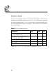
Transmit Antenna Select Lines
Pins 10, 22, 9, 21, and 8 are the high order bits of the hardware pins
that select the transmit antenna. Bit 0 is kept internal to the interroga-
tor. These lines are used to drive external multiplexers for multi-
antenna systems. They are controlled by:
1. Setting up the antenna select table in flash memory (if necessary)
using Load Antenna Table command.
2. Issue the Set Antenna Quantity command.
3. Default mode automatically cycles through all antennas. The
interrogator will freeze at a certain antenna selection by issuing
the Select Transmit Antenna command.
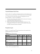
Peripheral Inputs
Pins 5, 17, 4, and 16 are TTL level inputs that can be read with the
Read Peripheral Inputs command.
* Note: VCC is nominally 5.0 volts.
Table 4. Input Characteristics
Description Min. Max. Units
Input high level voltage 2.0 VCC* Volts
Input low level voltage 0 0.8 Volts
Input signal transition
time
250 nS
Input leakage current -10 +10
µA
Input capacitance 10 pF