USER MANUAL EXPERIENCE INCREDIBLE PERFORMANCE
CONTENTS 1 INTRODUCTION ............................................................................................................................................... 4 2 INTERFACE DESIGN ......................................................................................................................................... 5 3 4 2.1 Connectivity.............................................................................................................................................. 6 2.
Copyright © 2017- www.SingleTact.com pg.
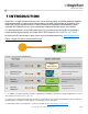
1 INTRODUCTION SingleTact is a single element tactile pressure sensor that accurately and reliably quantifies applied force combined with a simple interface board offering a 0 to 2V analog output for immediate Data Acquisition (DAQ) integration and an I2C based interface for integration into embedded systems. Standard and Calibrated sensors (with matched pre-calibrated interface board) are available.
2 INTERFACE DESIGN Copyright © 2017- www.SingleTact.com pg.
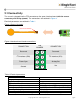
2.1 Connectivity The sensor is plugged into the FFC connector on the green interface board (with the sensor connector pads facing upward). The connections are outlined in Figure 4. Electrical parameters are outlined in Table 1. Figure 3 Sensor Assembly Note via orientation MCU SingleTact.
2.2 Analog Interface The analog output swings from 0 to 2V, with the valid working output ranging from 0.5V to 1.5V as shown in Figure 5. As pressure increases beyond the full scale range (FSR) the output will increase to 2V and then limit. The sensor should be unloaded at power on to allow the sensor’s baseline to be registered correctly. NOTE: An output below 0.5V may indicate negative pressures, which occur when the sensing area is under tension.
Figure 6 DAQ Connection Requirements CONNECTION PIN NUMBER CONNECTION No Connect 5 4 No Connect No Connect 6 3 No Connect No Connect 7 2 Analog Out Ground 8 1 Vcc 2.3 I2C Interface The SingleTact I2C interface supports the standard (100 Kbits/s) clock rate in 7-bit address mode. The SCL and SDA lines must be pulled up to the bus voltage which can be between 3V and 5V. Please refer to the I2C specification for bus protocol implementation & pull-up value considerations.
NOTE: It is the Users responsibility not to write to any Reserved locations.
BYTE 9 SETTING Capacitive Sense (Output Current) Default 0x00 *1 10 Output digital scaling MSB 11 Output digital scaling LSB 12 Number of elements, must be 1 13 Reserved 14 Delimiter – leave as 0xFF 15 First element to scan, set to 0 16-39 Reserved 40 Delimiter – leave as 0xFF 41 Sensor baseline MSB 42 Sensor baseline LSB 43-90 Reserved 91 Delimiter – leave as 0xFF 92-127 Reserved 128 Frame index MSB (increments on each new reading) 129 Frame index LSB (increments on each new
BYTE SETTING 133 Sensor output LSB 134 - > 191 Reserved *1 Should only be used as a coarse estimate as it is subject to drift. 2.4 I2C Operations I2C SingleTact supports three I2C operations: Write, Read Request and Read. 2.4.1 I2C Write Operation I2C bus Transfer: Master Write to Slave. This command writes values to the register block. All writes also update the internal flash memory so settings are persistent through a power cycle.
2.4.2 I2C Read Request Operation I2C bus Transfer: Master Write to Slave. This command sets the read location (register block offset) and read length for a following Read operation. Table 4 Read Request Operation Data Packet Format BYTE TO SENSOR 0 0x01 1 Read offset in register block 2 Number or bytes to read (1 – 32) 3 0xFF – end of packet delimiter 2.4.3 I2C Read Operation I2C bus Transfer: Master Read from Slave.
Reading outside of the valid range will fail. I2C slave Read operations simply return the register data values up to the number of requested bytes (32 max) in the data packet. NOTE: A sensor output reading below 0x0100 may indicate negative pressures, which occur when the sensing area is under tension. This should be avoided since it can damage the internal structure of the sensor. NOTE: Sensor over pressure should be limited to less than 3x FSR to avoid damaging the sensor.
The frame synchronization output (Frame Sync, Figure 4) goes high each time a new measurement is available. This can be used to synchronize the I2C communications channel to the capacitance sensor. Alternatively, the sensor might be polled as quickly as possible over I2C. Since the frame index increments with each frame it can be used to identify duplicate or missing data readings. 2.6 Product Categories Standard sensors will perform typically to their specified force range.
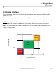
3 TROUBLESHOOTING SingleTact Copyright © 2017- www.SingleTact.com pg.
3.1 Arduino UNO not detected by PC. Arduino UNO requires to install a driver to communicate over USB port. Follow the step-by-step instruction from https://www.arduino.cc/en/Guide/HomePage. 3.2 Invalid setting error on PC (Popup reports” Failed to set”). Likely reason: faulty pin connection. 3.3 No Analog output (remains at 0V). Check wire connections and ensure that you are powering the sensor. Likely reasons: Power, Ground or output connection in the wrong place. power supply is off or faulty.
4 EXAMPLE USE CASE Copyright © 2017- www.SingleTact.com pg.
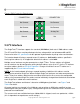
4.1 PC and Arduino Example An Arduino UNO board can be used to implement a USB serial interface to SingleTact. The code for an Arduino application (source) and an associated .NET based PC DAQ GUI application (both Windows executable and source) can be downloaded via www.singletact.com. Once the Arduino board has been programmed with the SingleTact firmware (see Programming the Arduino UNO with SingleTact Example) the PC application can be run to visually observe the sensor results.
Figure 9 SingleTact and Arduino UNO Connection CONNECTION PIN NUMBER CONNECTION No Connect 5 4 No Connect Arduino UNO pin A4 6 3 Arduino UNO pin A5 No Connect 7 2 No Connect Arduino UNO GND pin 8 1 Arduino UNO 5V pin To run the Windows GUI application: Open the PCExecutable folder. Run SingleTact Demo.exe to bring up the demonstration application. Figure 10 Demo of PC DAQ software *Note: Reference Gain will automatically change depending on the sensor size.
4.2 Programming the Arduino UNO with SingleTact Example This process outlines how to program the Arduino UNO with SingleTact example firmware. 1. Download and install the Arduino Software from: https://www.arduino.cc/en/Main/Software 2. Download the Arduino firmware (ExampleArduinoInterface) from: www.singletact.com 3. Connect the Arduino to the PC using the supplied USB cable. 4.
Figure 12 Arduino integrated development environment Figure 13 Compiling and uploading the SingleTactDemo.ino file Copyright © 2017- www.SingleTact.com pg.
4.3 Arduino Demo Outline The diagrams in this section provide an outline of the Arduino demo functionality as described in the previous section. In this case the PC to Arduino interface was setup to mirror the I2C interface, keeping the Arduino code as simple as possible.
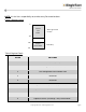
On the host, the Arduino appears as a virtual RS-232 serial device. Data is sent to/from the Arduino using a serial API, such as the one available in .NET. The Arduino calculates a timestamp for each packet using the Arduino’s crystal controlled oscillator. This can be used as the time for each sensor. The serial commands, which mirror the raw I2C commands (as shown in blue in Figure 16), are outlined in the following tables. Header and footer bytes are added to easily delimit serial packets.
Figure 16 Serial packet structure (sent to Arduino) BYTE FROM PC TO ARDUINO 0 Header = 0xFF 1 Header = 0xFF 2 Header = 0xFF 3 Header = 0xFF 4 I2C address of sensor 5 Timeout (in 100ms increments) 6 ID (echoed in reply) 7 Read (0x01) or Write (0x02) 8 Read/ write location 9 N bytes to read/ write (max 32) Data to write 10-> (10 + N-1) 0 bytes for read request 11 + N 0xFF – signifies end of packet 12 + N Footer = 0xFF 13 + N Footer = 0xFF 14 + N Footer = 0xFF 15 + N Footer = 0xF
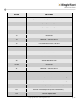
Figure 17 Serial packet structure (sent from Arduino) BYTE FROM ARDUINO TO PC 0 Header = 0xFF 1 Header = 0xFF 2 Header = 0xFF 3 Header = 0xFF 5 1 if timeout exceeded 6 ID (echoed transmit ID) 7 Timestamp MSB 8 Timestamp 9 Timestamp 10 Timestamp LSB 11 N I2C bytes to be sent (max 32) 12 -> 12+N I2C data 13+N Footer = 0xFE 14+N Footer = 0xFE 15+N Footer = 0xFE 16+N Footer = 0xFE Copyright © 2017- www.SingleTact.com pg.
4.4 Example .NET API This section provides some detail on the .NET API used to construct the PC GUI application. Download the .NET Interface and demo application from www.singletact.com. For convenience the low level PC interface is encapsulated in two .NET components. 1. ArduinoSingleTactDriver – The basic Arduino interface. The user must create one of these. 2. SingleTact – There can be multiple SingleTacts each with their own I2C address.
5 Resources SingleTact homepage http://www.singletact.com/ I2C-bus specification and user manual VERSION 6, April 2014 http://www.nxp.com/documents/user_manual/UM10204.pdf Arduino home https://www.arduino.cc/ Microsoft .NET Framework https://www.microsoft.com/net Copyright © 2017- www.SingleTact.com pg.
6 Glossary API CDC DAQ FFC FSR I2C IDE LSB MSB .NET NVM RS-232 Application Program Interface Capacitance to Digital Converter Data Acquisition Flexible Flat Cable (connector) Full Scale Range Inter IC bus Integrated Development Environment Least Significant Byte Most Significant Byte A Microsoft .NET software framework Non-Volatile Memory A serial communications standard Copyright © 2017- www.SingleTact.com pg.
7 Revision History 7.1 Revision 2.0 1) Removed Section 3 Updating the Interface Board. 2) Updated Table 1 accessibility to interface board design detail. 7.2 Revision 2.1 1) 2) 3) 4) 5) Added Revision History. Section 1: Referenced Calibrated and Uncalibrated product options. Figure 2: Fixed the link in footnote 3. Table 1: Added I2C Sensor Output range.
Copyright © 2017- www.SingleTact.com pg.