
Mounting Methods

SINGLETACT MOUNTING METHODS
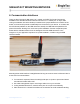
1. Introduction
There are a number of ways to integrate SingleTact sensors into your application, but deciding
on the best method is not always straightforward. Challenges may be faced with sensor
positioning, electronics mounting, and/or connections to your controller. This application note
covers several different methods for achieving optimal sensor placement.
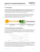
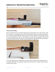
The SingleTact anatomy consists of three main parts: the SingleTact sensor, the SingleTact
electronics, and the communication interface for reading out the pressure data. There are
mounting considerations to each part that will be covered in this note. Below, a 15mm
SingleTact sensor and a standard electronics board is depicted.
SingleTact Sensor Electronics Communication Interface
(8mm or 15mm) (Standard or USB) (I
2
C, Voltage, or USB)
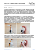
2. Sensor Mechanical Considerations
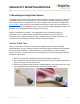
The construction of the SingleTact sensor consists of a top electrode, a sensor dielectric, and a
bottom electrode, sandwiched together with adhesive. Therefore, it is best to avoid applying
shearing forces to the sensor, and instead applying direct forces perpendicularly and evenly
across the sensor head.
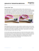
Another action to avoid is bending the sensor if possible, because when bent, one electrode will
be in compression while the other will be in tension, and this causes shearing to occur between
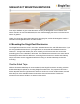
the two electrodes. If bending is necessary to fit the sensor into your application, keep the
circular portion (the active sensing region) as flat as possible, while applying the bend along the
tail end of the sensor. Keep the bend radius greater than 3 mm.
www.SingleTact.com ST_AN_003 Page 1