
Instructions / Assembly

ENGLISH
11
Water Supply Lines are not included. Please
consult manufacturer and/or its instructions for
the correct method of installation of supply lines
and ttings.
CAUTION: Incorrect application of supply lines and
ttings may result in the failure or leak of the supply lines
and ttings.
12
13
14
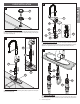
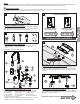
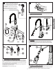
11 WATER SUPPLY CONNECTIONS
A.Thread inlet connectors (11A) into Water Supply Lines (11B).
B.Remove Protective Cap (11F). Gently separate HOT and COLD Faucet Inlets (11C),
approximately 1 in. (26 mm) apart. Connect Water Supply Lines (11B) onto Faucet Inlets
(11C). Hot Water supply goes to hot inlet tting indicated by red tag (11D).
C.Insert Clip (11E) into Inlet Connector Holes (11F) to secure water supply lines, as shown.
WARNING: Do not twist Faucet Inlets.
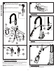
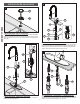
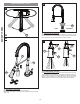
12 UNIT START UP
Turn on hot and cold water supplies, and check for leaks above and below the sink
13 FLUSHING
By rotating the Lever Handle (13A) away from the Faucet Body (13B), the valve will be
activated allowing water to ow. The water ow will increase by continuing to rotate the
Lever Handle (13A). Run water for one minute. Repeat in hot and cold positions.
14 ATTACH SPRAY HEAD
Attach Spray Head (14A) to the Hose (14B) by turning Spray Head (14A) clockwise.
Caution: do not over tighten sprya head and hose.
4
HOT
1” Max.
(26 mm)
COLD
11C
11A
11C
11B
11E
11F
11A
11B
11B
11B
11B
11E
11A
11F
11D
11A
11C
A
B
C
13A
13B
13A
14B
14A
OPEN