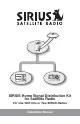
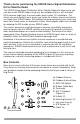
SIRIUS Home Signal Distribution Kit for Satellite Radio For Use With One or Two SIRIUS Radios Installation Manual
Thank you for purchasing the SIRIUS Home Signal Distribution Kit for Satellite Radio The SIRIUS Home Signal Distribution Kit for Satellite Radio will allow you to connect one or two SIRIUS radios using only one outdoor antenna, with standard RG-6 antenna cable wire, the same cable used in cable TV installations. This allows you great flexibility as to where you locate the outdoor antenna and where you locate your SIRIUS radios.
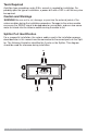
Tools Required A phillips-type screwdriver and a 3/8 in. wrench is needed for installation. Depending upon the type of installation, a power drill with a 3/32 in. drill bit may also be required. Caution and Warnings WARNING: Be sure not to cut, damage, or puncture the external jacket of the antenna cables during the installation procedure.
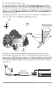
Materials Required and Installation Considerations In order to install the antenna you will need to purchase several lengths of RG-6 antenna cables to complete your installation. The following illustration shows a typical home installation. SATELLITE OUTDOOR ANTENNA SATELLITE RADIO Adapter Cable SATELLITE RADIO Adapter Cable SPLITTER S Cables will be needed for the following: 1. A length of RG-6 cable to go from the SIRIUS outdoor antenna to the location of the Splitter. 2.
RG-6 cable is typically sold in lengths of 25, 50, or 100 ft., all with “F” type connectors on each end. These cables may be purchased at your local hardware store, home center, or electronics retailer. The combined length of the RG-6 cables from the outdoor antenna to each SIRIUS radio should not exceed 150 ft., as shown in the preceding illustrations. The overall length for your particular installation may be less than 150 ft.
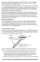
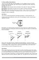
on the antenna base and align the screw holes in the mounting bracket with the screw hole in the antenna arm. 4. When the screw hole is aligned, re-insert screw B and snug it until it is tight. 1. 2. BASE ARM Incorrect C B Remove Screw Correct Verify the correct orientation of the antenna arm and antenna base 3. 4. Slide the antenna arm over the antenna base mounting bracket Align the screw hole B Re-insert screw and tighten 2.
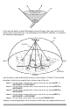
No obstructions to the sky within this area If you cannot obtain a clear 360 degree view of the sky, then you must at least have a clear view of the sky in the direction of the SIRIUS satellites, as shown in the following map diagram. SKY NORTH WEST 1 4 5 EAST 3 2 HORIZON SOUTH Use the above map and find the area you are located in (1 to 5).
the sky in the direction for your area. For example, suppose you live in Area 2. You determined that your antenna will need to have a clear view of the sky facing North or Northeast. The exact direction is determined by your specific location in Area 2 relative to the X on the map: If you live in Texas, you will need a more North facing clear view of the sky whereas if you live in southern California, you will need a more Northeast facing clear view of the sky.
3. Antenna Mounting Options There are three possible mounting options for the outdoor antenna, and the antenna mounting location you have chosen may determine which mounting methods you can use: Wall Mount: Mounting the antenna directly on the side of a home or building. Roof Mount: Mounting the antenna on the roof of a home or building.
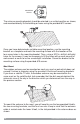
MOUNTING HOLES The antenna mounting bracket should be oriented in a vertical position as shown, and mounted directly to the building or home using the provided #10 screws. Once you have determined a suitable mounting location, use the mounting bracket as a template and mark the mounting surface with the location of the four screw holes in the mounting bracket. Then, using a 3/32 in. drill bit, drill pilot holes for the screws.
Slide one of the U-bolts through the holes at the top of the mounting bracket. Then slide one of the mounting brackets over the two legs of the U-bolt. Next, screw the hex nuts on each leg until they are snug. Do not yet tighten the hex nuts beyond finger tight. Repeat this procedure with the other U-bolt. When all the hex nuts are snug, verify that the antenna is facing the correct direction and begin tightening each hex nut with a 3/8” wrench.
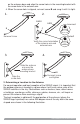
SKY HORIZONTAL LEVEL Antenna Pod 1 2 Adjustment Screw Adjustment Screw Slightly loosen the adjustment screws and position the antenna so that the top of the antenna pod is level, with the top of the pod horizontal to the sky as shown. When the antenna is adjusted correctly, tighten the adjustment screws but be careful not to overtighten them. Continue with the next section for installations with exposed wiring, or the section following for installations with hidden wiring.
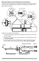
OUT1 IN OUT2 you are locating the Splitter. When routing the antenna cable, be careful not to pinch, squash, kink, or crimp the cable, or cut, damage, or puncture the external jacket of the antenna cable. 4. Connect the cable from the antenna to the IN port on the Splitter as shown. (Refer to page 3 for the Splitter port identification.) Note that you must use the Splitter even if you are only connecting one SIRIUS radio. { Use terminator if no second receiver OUT1 IN OUT2 5.
OUT2 IN OUT1 OUT1 IN OUT2 If you are connecting one SIRIUS radio, the completed installation should be as illustrated below: 14 Home Distribution Kit Installation Manual
Troubleshooting SIRIUS radio displays “Antenna Error” or “Check Antenna” message. Check the antenna cable connections to be sure they are connected tightly. SIRIUS radio displays “No Signal” or “Acquiring Signal” message. The radio is not receiving a good SIRIUS signal. Check that the antenna has a clear view of the sky, and that the antenna is pointed in the direction of the SIRIUS satellites. (See the section titled, Antenna Installation.
SIRIUS Satellite Radio 1221 Avenue of the Americas New York, NY 10020 (888) 539-7474 www.sirius.com © 2007 SIRIUS Satellite Radio Inc. (SIRIUS Home Signal Distribution Kit for Satellite Radio 100107a) ® “SIRIUS” and the SIRIUS dog logo are registered trademarks of Sirius Satellite Radio Inc.
SHDK1 90 DAY LIMITED WARRANTY Satellite Radio Accessory AUDIOVOX ELECTRONICS CORPORATION (the Company) warrants to the original retail purchaser of this product that should this product or any part thereof, under normal use and conditions, be proven defective in material or workmanship within 90 days from the date of original purchase, such defect(s) will be repaired or replaced with new or reconditioned product (at the Company's option) without charge for parts and repair labor.