Clear & Crisp High Resolution Color Camera SDC-313B User’s Manual SALES NETWORK • SAMSUNG TECHWIN CO., LTD. 145-3, Sangdaewon 1-dong, Jungwon-gu, Seongnam-si, Gyeonggi-do 462-703, Korea TEL : +82-31-740-8137~8139 FAX : +82-31-740-8145 • SAMSUNG OPTO-ELECTRONICS UK, LTD. Samsung House, 1000 Hillswood Drive, Hillswood Business Park Chertsey, Surrey KT16 OPS TEL : +44-1932-45-5308 FAX : +44-1932-45-5325 www.samsungtechwin.com www.samsungcctv.com • TIANJIN SAMSUNG OPTO-ELECTRONICS CO., LTD.
Thank you for purchasing a SAMSUNG CCD CAMERA. Before operating the camera, confirm the camera model and proper input power voltage. In order to that you can understand this manual thoroughly, we'll introduce our model description. ■ SDC-313B SERIES • NTSC MODEL SDC-313BNA Samsung Techwin cares for the environment at all product manufacturing stages to preserve the environment, and is taking a number of steps to provide customers with more environment-friendly products.
Contents 8 Precautions • LENS (selection) • SHUTTER (condition and speed control) 20 20 21 23 24 • WHITE BALANCE control 25 • BACKLIGHT (Backlight Compensation) 26 • AGC (Auto Gain Control) 27 • SSNR (Samsung Super Noise reduction) • SENS-UP (Low illuminance) 28 29 • SPECIAL 30 • EXIT 35 Camera Operation Menu Settings Component 10 Name and Function of Each Parts 11 11 12 13 14 FRONT SIDE BOTTOM BACK 15 Installation 15 18 19 Lens Connecting to a Monitor Connecting to Power COLOR CCD
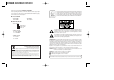
Features Warning The camera needs periodic inspection. Horizontal Resolution 530 TV Lines High Sensitivity Clear image quality has been achieved by employing a CCD with 410,000 pixels(NTSC), 470,000 pixels (PAL), which provides a horizontal resolution of 530 TV lines. The built-in high sensitivity COLOR CCD enables a clear image even in 0.002 Lux(SensUp) illumination. Contact an authorized technician for inspection. Stop using your camera when you find a malfunction.
Precautions Do not install under extreme temperature conditions. Do not install in high humidity environment. Use only under temperature conditions between -10˚C and +50˚C. Provide good ventilation when using in high temperature conditions. Do not install under unstable lighting conditions. May lower image quality. Do not drop the camera or subject it to physical shock. May cause a product malfunction. Never keep the camera face to strong light directly. May damage the CCD.
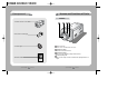
Names and Functions of Parts Component FRONT 1. HIGH RESOLUTION COLOR CAMERA 2. Auto iris lens connection plug 3. C-Mount adaptor CCD protection cap Please cover the CCD SENSOR when not using it. C-Mount lens adaptor Please attach the C-Mount lens here. CS-Mount lens adaptor Please remove the C-MOUNT lens adaptor and then attach it. Back Focus clamp screw Please loosen the clamp screw with a screwdriver before adjusting the Back Focal length. 4.
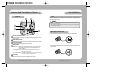
Names and Functions of Parts SIDE BOTTOM Mounting bracket screw hole Please use the screw hole when fixing the camera onto the mounting bracket. Please use the clamp screw as specified below. Auto iris lens connector This is the connection terminal for the auto iris lens. L 1/4"-20 UNC (20 THREAD) L:4.5mm±0.2mm (ISO standard), or 0.197" (ASA standard) The mounting bracket can be separated and attached to the top of the camera.
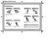
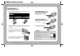
Names and Functions of Parts Installation Lens BACK Lenses are sold separately. Lenses such as an auto iris lens, CS-Mount lens and C-Mount lens can be used. Notes • Please keep the lens clean. • Any foreign objects and fingermarks on the lens can cause inferior image quality in low light level conditions. When using an auto iris lens 1. Please peel off about 8mm of the outer skin of the auto iris lens cable.
Installation 3. Please remove the cover of the auto iris lens connection plug and solder the lens cable to the connector pin in the plug. LENS Pin No. DC DampingDamping+ Drive+ Drive- No.1 Pin No.2 Pin No.3 Pin No.4 Pin VEDIO Red (power) NC White (video signal) Black (GND) Lens cable No.3 Pin No.1 Pin Connector When using a C-Mount lens Please take off the CCD protection cap and attach the C-Mount lens to the camera by screwing it in clockwise. C-mount adaptor When using a CS-Mount lens 1.
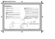
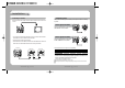
Installation Connecting to a Monitor Connecting to Power Please connect the video output terminal located on the back of the camera to the monitor. Please check the model type and standard power requirement before connecting to power. AC Power Type (AC 24V, 300mA) The recommended adaptor specification for SDC-313BNA is AC 24V / 300mA. CCD Camera Monitor • The connection method varies depending on the type of monitor and accessories. Please refer to the user's manual for each instrument.
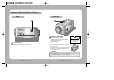
Camera Operation Camera Operation Menu Settings Settings can be made using the 5 buttons located on the back of the camera.
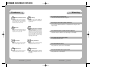
Camera Operation Select any function you wish to operate by using the UP and DOWN buttons. SETUP LENS SHUTTER WHITE BAL. BACKLIGHT AGC SSNR SENS-UP SPECIAL EXIT LENS (selection) DC --ATW OFF MIDDLE LOW OFF Modes can be changed using the LEFT and RIGHT buttons. This function is used to adjust the brightness of the screen. 1. When the SETUP menu is displayed on the screen, please position the arrow to point to 'LENS' by using the UP and DOWN buttons. 2.
Camera Operation SHUTTER (condition and speed control) 1. When the SETUP menu is on the screen, please position the arrow to point to 'SHUTTER' by using the DOWN button. 2. Please select the shutter mode by pressing the LEFT or RIGHT button. FLK: Please select 'FLK' mode when flickering occurs on the screen, due to an imbalance between illumination and frequency. NTSC Model:1/100, PAL MODEL: 1/120 WHITE BALANCE control The screen color can be adjusted by using the WHITE BALANCE function. 1.
Camera Operation BACKLIGHT (Backlight Compensation) When there is a strong backlight behind the object, clear images of the background as well as the object can still be obtained by using the BACKLIGHT function. 1. Please position the arrow to point to 'BACKLIGHT' on the SETUP menu by using the UP and DOWN buttons. 2. Please select the mode you wish to operate by pressing the LEFT or RIGHT button. SETUP LENS SHUTTER WHITE BAL.
Camera Operation SSNR (Samsung Super Noise reduction) The background noise in the low light level decreases automatically as the level of gain changes. 1. Please position the arrow to point to 'SSNR' on the SETUP menu by using the UP and DOWN buttons. 2. Please select the mode you wish to operate by pressing the LEFT or RIGHT button. SENS-UP (Low illuminance) SENS-UP helps maintain a bright, clear screen image by automatically detecting changes in the level of light in low light level conditions. 1.
Camera Operation 3) Please press the SETUP button. SPECIAL 1. Please position the arrow to point to 'SPECIAL' on the SETUP menu by using the UP and DOWN buttons. 2. Please select the mode you wish to operate by pressing the UP or DOWN button. SPECIAL CAMERA ID OFF SYNC INT MOTION DET OFF PRIVACY OFF MIRROR OFF SHARPNESS ON RESET RETURN CAMERA ID: If the ID is input, the camera ID appears on the monitor. 1) Please position the arrow to point to 'CAMERA ID' by using the UP or DOWN button.
Camera Operation 5) When a name has been chosen, please select a position for the name display. Please move the cursor onto 'POS' and then press the SETUP button. Camera ID ABCDEFGHIJKLM NOPQRSTUVWXYZ abcdefghijklm nopqrstuvwxyz -. 123456789 CLR POS END The name will appear at the top left hand corner. Notes • When the power frequency is 50Hz, you can not use line-lock mode (NTSC MODEL). • When the power frequency is 60Hz, you can not use the line-lock mode(PAL MODEL).
Camera Operation PRIVACY: This modes conceals the areas you do not wish to appear on the screen. - OFF : Cancels the PRIVACY mode. - ON : Operates the PRIVACY mode. •Please press the SETUP button. •Please select the area you do not wish to appear from the 4 areas in AREA SEL mode. •Please select ON mode for the chosen area. •Please adjust the size of the area to be concealed by using the UP, DOWN, LEFT or RIGHT button.
Troubleshooting If you have trouble operating your camera, refer to the following table. If the guidelines do not enable you to solve the problem, contact an authorized technician. Problem Solution Nothing appears on the screen. The video image is not clear. The screen is dark. There is a problem with the camera operation. The camera surface is too hot and black stripes appear on the screen. • Please check the power connection. • Please check the video signal line connection.
DECLARATION OF CONFORMITY Specifications Item SDC-313BNA POWER C C D S y n c AC 24V / 3.5W DC12V/2.5W Total Pixels 811(H) x 508(V) 795(H) x 596(V) Effective Pixels 768(H) x 494(V) 792(H) x 582(V) Sensor Application of Council Directive(s) 89 / 336 / EEC Manufacturer's Name SAMSUNG TECHWIN CO., LTD Manufacturer's Address KYUNGNAM, KOREA, 641-120 2:1 Interlace Synchronization Internal / Line Lock 0~359˚ (Adjustable) Internal fixed Frequency Horizontal: 15.734 KHz / Vertical: 59.