3EM21522AAAA Issue 1, March 2008 6 MAINTENANCE 6.1 GENERAL Maintenance DTR-0200-SA-SIRIUS This section addresses repeater faults, fault identification, fault troubleshooting, removal and replacement of faulty item(s), and final system testing. 6.
Maintenance DTR-0200-SA-SIRIUS 3EM21522AAAA Issue 1, March 2008 6.6.2 Local Troubleshooting Overview Local troubleshooting is performed at the repeater site by a dispatched technician using a PC, GUI screens (or CLI), and external test equipment. When the fault is corrected, the technician follows on with a system test.
EM21522AAAA Issue 1, March 2008 Maintenance DTR-0200-SA-SIRIUS Opening the Door – first release the captive locking screw(s) then undo the draw latches. Closing the Door – first secure the draw latches then tighten the captive locking screw(s).
Maintenance DTR-0200-SA-SIRIUS 3EM21522AAAA Issue 1, March 2008 NMC coordination must be accomplished prior to repeater being switched to Local operating condition. This will prevent conflicting actions between the NMC and on-site operator(s) and preclude possible personal injury and/or equipment damage. • Switch the repeater to the Local operating condition.
3EM21522AAAA Issue 1, March 2008 Maintenance DTR-0200-SA-SIRIUS WARNING Possibility of Damage to Equipment POSSIBILITY OF EQUIPMENT AND/OR STRUCTURE DAMAGE DUE TO FIRE. Any fuse replacement must be with an exact fuse value (size, rating, capacity) as the fuse being replaced. 6.
-6 This page intentionally left blank.
3EM21522AAAA Issue 1, March 2008 Maintenance DTR-0200-SA-SIRIUS Chart 1 Remove and Replace signal Processing Unit (SPU) Main power to repeater must be off. STEP PROCEDURE REMOVAL 1 Open front and rear doors a To open front door Release two locking screws then release two door latches. b To open rear door Release one locking screw then release two door latches 2 Coordinate with NMC and switch repeater to local operating condition.
Maintenance DTR-0200-SA-SIRIUS 3EM21522AAAA Issue 1, March 2008 Figure 6 - 2 SPU Rear Connector Panels STEP PROCEDURE CONT. REPLACEMENT 8 Insert new SPU into cabinet. 9 Reconnect all cables. 10 Switch ON commercial power source breaker and remove danger sign. 11 Switch ON main PDU circuit breaker. 12 Switch ON remaining PDU circuit breaker. 13 Perform parameter changes. When the SPU is replaced, various parameters must be changed. The following steps identify the required parameter changes.
3EM21522AAAA Issue 1, March 2008 STEP Maintenance DTR-0200-SA-SIRIUS PROCEDURE CONT. b ALARMS • ALARMS>Alarm Properties (set SIRIUS specified alarm traps ON or OFF for NMS alerting). c NMS USERS • NMS USERS>User Properties Auth Type = SHA Priv Type = DES. d SYSTEM PARAMETERS • SYSTEM PARAMETERS>Network Parameters (reset per SIRIUS network manager information). • SYSTEM PARAMETERS>SNMP Parameters (set SNMP Traps to ON and enter SNMP server IP address).
6-10 This page intentionally left blank.
3EM21522AAAA Issue 1, March 2008 Maintenance DTR-0200-SA-SIRIUS Chart 2 Remove and Replace High Power Amplifier (HPA) Main power to repeater must be off. This procedure requires a 1 1/4” open end wrench with an overall length of no more than 4 inches to disconnect and reconnect the RF OUT cable. STEP PROCEDURE REMOVAL 1 Open front and rear doors. a To open front door Release two locking screws then release two door latches.
Maintenance DTR-0200-SA-SIRIUS 3EM21522AAAA Issue 1, March 2008 Figure 6 - 3 HPA Rear Panel Connectors STEP PROCEDURE CONT. REPLACEMENT 8 Insert new HPA into cabinet. WARNING Possibility of Damage to Equipment RF Connector must be installed properly to prevent RF leakage and/or arcing. 9 Reconnect all cables (use 1 1/4” open-end wrench on RF OUT cable connector). 10 Switch ON commercial power source breaker and remove danger sign. 11 Switch ON main PDU circuit breaker.
3EM21522AAAA Issue 1, March 2008 Maintenance DTR-0200-SA-SIRIUS Chart 3 Remove and Replace RF Detector(s) Main power to repeater must be off. Prior to removal of detector(s), tag each to identify which is the forward RF detector and which is the reflected RF detector. Failure to install detectors correctly will cause the wrong feedback signals to be transmitted to the main controller. This in turn will cause HPA power problems and inaccurate power readings.
Maintenance DTR-0200-SA-SIRIUS STEP 3EM21522AAAA Issue 1, March 2008 PROCEDURE REMOVAL 1 Open front and rear doors. a To Open Front Door Release two locking screws then release two door latches b To Open Rear Door Release one locking screw then release two door latches. 2 Coordinate with NMC and switch repeater to Local operating condition. 3 Switch OFF all repeater PDU circuit breakers, switching repeater main breaker last.
3EM21522AAAA Issue 1, March 2008 STEP Maintenance DTR-0200-SA-SIRIUS PROCEDURE CONT. REPLACEMENT 9 Connect detector cable(s) to SPU controller rear panel (FWD RF DETECTOR, REF RF DETECTOR) ensuring correct detector connects to correct connector. Refer to NOTE preceding step 5. 10 Connect RF detector(s) to RF coupler and tighten SMA connector(s). Ensure that proper detector is connected to the proper connector on the RF coupler. Refer to NOTE preceding step 5 above.
6-16 This page intentionally left blank.
3EM21522AAAA Issue 1, March 2008 Maintenance DTR-0200-SA-SIRIUS Chart 4 Remove and Replace RF Coupler Main power to repeater must be off. This procedure requires a 1 1/8” open end wrench with an overall length of no more than 5 inches and a maximum thickness of 1/8” to disconnect and reconnect the RF Coupler securing nuts.
Maintenance DTR-0200-SA-SIRIUS STEP 3EM21522AAAA Issue 1, March 2008 PROCEDURE REMOVAL 1 Open front and rear doors. a To Open Front Door Release two locking screws then release two door latches. b To Open Rear Door Release one locking screw and then release two door latches. 2 Coordinate with NMC and switch repeater to Local operating condition. 3 Switch OFF all repeater PDU circuit breakers switching repeater main breaker last.
3EM21522AAAA Issue 1, March 2008 STEP Maintenance DTR-0200-SA-SIRIUS PROCEDURE CONT. REPLACEMENT 10 Install coupler and tighten connecting nuts and elbow adapter screws. 11 Connect RF detectors to new coupler ensuring that proper detector is connected to the proper connector. Refer to NOTE preceding step 6 above. 12 Connect RF monitor cables to the RF coupler ensuring that proper cable is connected to proper connector. Refer to NOTE preceding step 6 above.
6-20 This page intentionally left blank.
3EM21522AAAA Issue 1, March 2008 Maintenance DTR-0200-SA-SIRIUS Chart 5 Remove and Replace Rear Door Intake Fan(s) Main power to repeater must be off.
Maintenance DTR-0200-SA-SIRIUS STEP 3EM21522AAAA Issue 1, March 2008 PROCEDURE REMOVAL 1 Open front and rear doors a To Open Front Door Release two locking screws then release two door latches. b To Open Rear Door Release one locking screw then release two door latches. 2 Coordinate with NMC and switch repeater to Local operating condition. 3 Switch OFF all repeater PDU circuit breakers switching main breaker last. 4 Switch OFF commercial power source breaker supplying power to repeater.
3EM21522AAAA Issue 1, March 2008 STEP Maintenance DTR-0200-SA-SIRIUS PROCEDURE CONT. REPLACEMENT 9 Install new fan on mounting studs. 10 Replace and tighten fan securing hardware. 11 Reconnect power wires to fan terminal block. 12 Switch ON commercial power source breaker and remove danger sign. 13 Switch ON main PDU circuit breaker. 14 Switch ON remaining PDU circuit breakers. 15 Set operating mode to Broadcast. 16 Coordinate with NMC and return repeater to Remote operating condition.
6-24 This page intentionally left blank.
3EM21522AAAA Issue 1, March 2008 Maintenance DTR-0200-SA-SIRIUS Chart 6 Remove and Replace Under Roof Exhaust Fan(s) Main power to repeater must be off.
Maintenance DTR-0200-SA-SIRIUS STEP 3EM21522AAAA Issue 1, March 2008 PROCEDURE REMOVAL 1 Open front and rear doors. a To Open Front Door Release two locking screws then release two door latches. a To Open Rear Door Release one locking screw then release two door latches. 2 Coordinate with NMC to switch repeater to Local operating condition. 3 Switch all repeater PDU circuit breakers to OFF, switching main breaker last.
3EM21522AAAA Issue 1, March 2008 Maintenance DTR-0200-SA-SIRIUS DTR-1094 10/31/07 Figure 6 - 9 Internal Wing Screws (4) Figure 6 - 10 External Eye Bolts and Spacers (2) 6-27
Maintenance DTR-0200-SA-SIRIUS 3EM21522AAAA Issue 1, March 2008 . Figure 6 - 11 Fan Terminal Block STEP PROCEDURE CONT. REPLACEMENT 10 Install new fan(s) on mounting studs. 11 Replace and tighten fan securing hardware. 12 Reconnect power wires to fan terminal block. 13 Reinstall cabinet roof (Figure 6 - 12) and roof securing hardware (Figure 6 - 13). When reinstalling the roof, the side with the larger nut plate goes to the front of the cabinet.
3EM21522AAAA Issue 1, March 2008 Maintenance DTR-0200-SA-SIRIUS Nut Plates DTR-1095 10/28/07 Figure 6 - 12 Roof Showing Nut Plates Figure 6 - 13 Roof Securing Hardware 6-29
Maintenance DTR-0200-SA-SIRIUS STEP 3EM21522AAAA Issue 1, March 2008 PROCEDURE CONT. 14 Switch on commercial power source main breaker and remove danger sign. 15 Switch on main PDU circuit breaker. 16 Switch on remaining PDU circuit breakers. 17 Set operating mode to Broadcast. 18 Coordinate with NMC and return repeater to Remote operating condition. 19 Close front and rear doors. a To Close Front Door Secure two door latches then tighten two locking screws.
3EM21522AAAA Issue 1, March 2008 Maintenance DTR-0200-SA-SIRIUS Chart 7 Remove and Replace Fan Relay R1 and/or R2 Main power to repeater must be off. Relay R1 controls the roof fans; relay R2 controls the rear door fans.
Maintenance DTR-0200-SA-SIRIUS STEP 3EM21522AAAA Issue 1, March 2008 PROCEDURE REMOVAL 1 Open front and rear doors. a To Open Front Door Release two locking screws then release two door latches. b To Open Rear Door Release one locking screw then release two door latches. 2 Coordinate with NMC to switch repeater to local operating condition. 3 Switch OFF all repeater PDU circuit breakers switching main breaker last. 4 Switch OFF commercial power source breaker supplying power to repeater.
3EM21522AAAA Issue 1, March 2008 STEP Maintenance DTR-0200-SA-SIRIUS PROCEDURE CONT. REPLACEMENT 8 Insert the new relay into its socket. 9 Replace metal securing strap on relay. 10 Insert SPU into cabinet. 11 Secure SPU by replacing mounting screws through front panel. 12 Reinstall all connecting cables to rear connectors of SPU. 13 Close rear cabinet door by securing two draw latches and then tightening door locking screw.
6-34 This page intentionally left blank.
3EM21522AAAA Issue 1, March 2008 Maintenance DTR-0200-SA-SIRIUS Chart 8 Remove and Replace Rear Door Air Filter Main power to repeater must be off.
Maintenance DTR-0200-SA-SIRIUS STEP 3EM21522AAAA Issue 1, March 2008 PROCEDURE REMOVAL 1 Open front and rear doors. a To Open Front Door Release two locking screws then release two door latches. b To Open Rear Door Release one locking screw then release two door latches. 2 Coordinate with NMC and switch repeater to Local operating condition. 3 Switch OFF all repeater PDU circuit breakers switching main breaker last.
3EM21522AAAA Issue 1, March 2008 Maintenance DTR-0200-SA-SIRIUS Figure 6 - 17 Air Filter Assembly Figure 6 - 18 Air Filter Assembly (Filter and Louver Plate) 6-37
Maintenance DTR-0200-SA-SIRIUS STEP 3EM21522AAAA Issue 1, March 2008 PROCEDURE CONT. REPLACEMENT 8 Install new filter onto louver plate. 9 Using five retaining screws, re-attach filter assembly to cabinet rear door. 10 Switch ON commercial power source main breaker and remove danger sign. 11 Switch ON main PDU circuit breaker. 12 Switch ON remaining PDU circuit breakers. 13 Set operating mode to Broadcast. 14 Coordinate with NMC and return repeater to Remote operating condition.
3EM21522AAAA Issue 1, March 2008 Maintenance DTR-0200-SA-SIRIUS Chart 9 Remove and Replace PDU Front Access Circuit Breakers Main power to repeater must be off. Figure 6 - 19 PDU Front Panel STEP PROCEDURE REMOVAL 1 Open front door. a To Open Front Door Release two locking screws then release two door latches. 2 Coordinate with NMC and switch repeater to Local operating condition. 3 Switch OFF all repeater PDU circuit breakers switching main breaker last.
Maintenance DTR-0200-SA-SIRIUS STEP 3EM21522AAAA Issue 1, March 2008 PROCEDURE CONT. 4 Switch OFF commercial power source breaker supplying power to repeater. 5 Hang “DANGER – DO NOT TURN ON – PERSONNEL WORKING” sign at commercial power source breaker. 6 From front of cabinet remove PDU securing screws. 7 Carefully pull the PDU away from the rack. The PDU can only be pulled out approximately six inches. 8 Remove the PDU face plate screws.
3EM21522AAAA Issue 1, March 2008 STEP Maintenance DTR-0200-SA-SIRIUS PROCEDURE CONT. REPLACEMENT 13 Insert new breaker; install and tighten breaker securing screws. 14 Connect and secure breaker wires. 15 Reposition face plate and secure with face plate screws. 16 Set PDU back into the cabinet and secure with mounting screws. 17 Switch ON commercial power source breaker and remove danger sign. 18 Switch ON PDU main circuit breaker. 19 Switch ON PDU remaining circuit breakers.
6-42 This page intentionally left blank.
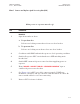
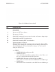
3EM21522AAAA Issue 1, March 2008 A REPEATER DIAGRAMS A.1 GENERAL Appendix A DTR-0200-SA-SIRIUS This section contains repeater support information and drawings. A.2 Title LIST OF DRAWINGS Drawing No. System Document Mapping ..................................................................3EM 04000 0000 ADZZA System Application Rules .................................................................... 3EM 04000 0000 BGZZA (Sheet 1 of 3) Transmit Antenna Configurations. ..............................
A-2 This page intentionally left blank.
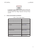
3EM21522AAAA Issue 1, March 2008 Appendix B DTR-0200-SA-SIRIUS B ALCATEL-LUCENT PART NUMBERS B.1 LRU PART NUMBERS See Table B-1 for Alcatel-Lucent LRU part numbers. Table B-1 Repeater LRU Part Numbers Item B.
Appendix B DTR-0200-SA-SIRIUS 3EM21522AAAA Issue 1, March 2008 Table B-2 Intermodule Connecting Cables (Continued) ALU P/N 3EM21711AA Connects To Connector Type SPU Modulator (Ethernet) RJ-45 Connects To SPU Controller (Ethernet) Ethernet Port on Modulator Connector Type RJ-45 Ethernet Port on Controller 3EM21711AA RJ-45 Connectors on both ends 3EM21711AA 06/30/07 3EM21713AA Junction Box (CPL FWD) N-Type Connector RF Coupler (FWD) SMA Straight Connector FWD on Junction Box Panel FWD RF C
3EM21522AAAA Issue 1, March 2008 Appendix B DTR-0200-SA-SIRIUS Table B-2 Intermodule Connecting Cables (Continued) ALU P/N Connects To 3EM21714AA BP Filter (RF IN) Connector Type 7/16 DIN Male Right Angle Connects To HPA (RF OUT) Connector Type 7/16 DIN Male RF OUT on HPA RF IN on Band Pass Filter 3EM21714AA SMA Connectors on both sides 3EM21714AA 06/30/07 3EM21715AA Junction Box (VSAT IN) T&B Snap-N-Seal Connector VSAT Connector on Junction Box VSAT RCVR (VSAT ANT) T&B Snap-N-Seal Conn
Appendix B DTR-0200-SA-SIRIUS 3EM21522AAAA Issue 1, March 2008 Table B-2 Intermodule Connecting Cables (Continued) ALU P/N Connects To 3EM21717AA HPA (IF-RS485) Connector Type DB-9, Male CONTROL IF on HPA Connects To SPU Controller (PA CONTROL) Connector Type DB-9, Female PA CONTROL on Connector 3EM21717AA DB-9 Connectors on both ends 3EM21717AA 06/30/07 3EM21718AA HPA (RF IN) N-Type Straight Cable Plug Up-Converter (RF OUT) SMA Straight Cable Plug RF IN on HPA RF OUT on Up-converter 3E
3EM21522AAAA Issue 1, March 2008 C Appendix C DTR-0200-SA-SIRIUS ALARM DESCRIPTION, LIKELY CAUSE, AND SUGGESTED RESPONSE Alarms are listed alphabetically by alarm names as they appear on the GUI Alarm screen Deviating above a positive or below a negative temperature threshold will cause an alarm as indicated in Table C-1. Following are the temperature thresholds for the repeater: C.1 HPA DEFAULT TEMPERATURE THRESHOLD • HPA Warning Low Temperature . . . . . . . . . . . . . . . . . . . . .
Appendix C DTR-0200-SA-SIRIUS C.4 3EM21522AAAA Issue 1, March 2008 ALARM TABLE See Table C-1 for alarm names, causes, and corrective responses. Table C-1 Alarms, Possible Causes, and Suggested Response Alarm Description Possible Cause 3.3V Voltage too high SPU 3.3V Voltage is too high >3.6V SPU Power Supply Fault Replace the SPU 5.0V Voltage too high SPU 5.0V Voltage too high >5.5V SPU Power Supply Fault Replace the SPU 12.0V Voltage too high SPU 12V Voltage is too high >13.
3EM21522AAAA Issue 1, March 2008 Appendix C DTR-0200-SA-SIRIUS Table C-1 Alarms, Possible Causes, and Suggested Response (Continued) Alarm Description Possible Cause Operator Response GPS Surveillance Error Problem detected on GPS receiver Problem detected on GPS receiver Replace SPU (Main Controller fault) Heartbeat Alarm notifies NMS that repeater is alive Transmission interval defined by “Heartbeat Pace” No action required HPA Comm Error No communication between HPA and Main Controller No
Appendix C DTR-0200-SA-SIRIUS 3EM21522AAAA Issue 1, March 2008 Table C-1 Alarms, Possible Causes, and Suggested Response (Continued) Alarm Description Possible Cause Operator Response HPA Temperature Fault HPA turns off HPA Temperature is above the Critical High Temperature level, +82°C. Check input, output ventilation vents. Verify fans are operational. If no fault found, replace HPA.
3EM21522AAAA Issue 1, March 2008 Appendix C DTR-0200-SA-SIRIUS Table C-1 Alarms, Possible Causes, and Suggested Response (Continued) Alarm Description Possible Cause Operator Response PA Module 0, 1, 2, 4, 5 or Driver Module TR2 Voltage Fault This alarm is triggered when the voltage on transistor 2 exceeds 32 volts or goes below 26 volts Wrong voltage on transistor 2 Replace HPA PA Module 0, 1, 2, 4, 5, or Driver Module TRI Current Fault This alarm is triggered when the current on transistor 1 ex
Appendix C DTR-0200-SA-SIRIUS 3EM21522AAAA Issue 1, March 2008 Table C-1 Alarms, Possible Causes, and Suggested Response (Continued) Alarm Description Possible Cause Operator Response Over Temperature Fault Ambient temperature is above the user defined threshold Roof exhaust fan(s) or rear door intake fan(s) inoperative. Check fans operation. Replace fan(s) where necessary.
3EM21522AAAA Issue 1, March 2008 Appendix C DTR-0200-SA-SIRIUS Table C-1 Alarms, Possible Causes, and Suggested Response (Continued) Alarm Description Possible Cause Operator Response Satellite Receiver Comm Error VSAT Receiver problem No VSAT input signal Check VSAT input signal level. If good VSAT signal is present, replace SPU SFN Timing Error Synchronization problem This alarm is typically raised in the beginning of the synchronization stage and shall disappear within 16 sec.
Appendix C DTR-0200-SA-SIRIUS 3EM21522AAAA Issue 1, March 2008 Table C-1 Alarms, Possible Causes, and Suggested Response (Continued) Alarm Description Possible Cause Operator Response VSAT LNB Over Current Antenna shorted Antenna shorted Investigate antenna & antenna cable.