
User Manual

SISTEMATICA S.p.A.
SISTEMATICA S.p.A.SISTEMATICA S.p.A.
SISTEMATICA S.p.A.
Pag. 3/4
Via S. Pertini, 17 – 12030 MANTA (CN) ITALY Tel. +39 0175 255.711 r.a. – Fax +39 0175 255.715
http://www.sistematica.it e-mail: info@sistematica.it
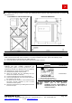
POSITIONING OF THE RECEIVER UNIT, DIMENSION AND DRILLING TEMPLATE
For a proper functioning, locate the receiver type CONTROLLER 20 with the cable output downwards, as shown in
the picture below:
POSITIONING OF THE RECEIVER UNIT
RECEIVER DIMENSION
DRILLING TEMPLATE DIMENSION
ANTENNA INSTALLATION
The CONTROLLER 32 is provided with an external antenna (STUB) with relative gasket. It must be mounted on the
SMA connectoron the back of the controller. For a correct installation procedure, perform the following steps:
1. Place the gasket ont the thread of the SMA connector;
2. Screw the antenna up to the bottom of the thread of the SMA connector .
FUSE REPLACEMENT
The system is automatically protected from power
overload and from possible short-circuit on
corresponding outputs. For further protection is also
provided an internal fuse within the box. For replacing
the damaged fuse, please proceed as follows:
1. Disconnect the power to the receiver;
2. Open the receiver box, by unsrewing the four
screws on the bottom of the box;
3. Locate the damage fuse on the receiver board;
4. Take the damaged fuse out of its holder and insert
the new fuse, (F1= 15 A);
5. Put power into the receiver; to check that the fuse
has been correctly replaced, try one or more
movements of the system;
6. Close the receiver box by screwing the four screw
removed at step 2.
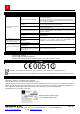
PRODUCT IDENTIFYING LABELS
Internal label
CNTR32: product model
S/N: product serial number
Cod.: product identification number
External label
Removal of the identifying labels
entails lapin of the guarantee
conditions and the responsabilità of
SISTEMATICA S.p.A. with respect to
component bodies