
User Manual

SISTEMATICA S.p.A. Pag. 2/4
Via S. Pertini, 17 – 12030 MANTA (CN) ITALY Tel. +39 0175 255.711 r.a. – Fax +39 0175 255.715
http://www.sistematica.it e-mail: info@sistematica.it
TECHNICAL FEATURES
• Manufacturer: SISTEMATICA S.p.A.
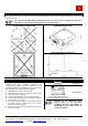
• Dimensions: 133,2x154,2x44
• Outputs number: up to 12
• Digital inputs number: up to 8
• IP protection: IP66
• Operating temperature: -20°C ÷ +70°C
• Power supply voltage: 12/24 V ±10%
• Current consumption (stanby): - 30 mA at 12 V
- 30 mA at 24 V
• Max current per channel: 2,8 A
• Max total current: 7 A
• Main connector: FCI-SICMA 24 Header pin
• Communication interface: CAN BUS
•
Can Bus addresses number: 16
• 8 bit microcontroller
• Reverse battery protection
• Internal antenna
• External antenna (option, ask for availability at
info@sistematica.it)
SYSTEM CODING
Coding the system is an operation that is only necessary when the receiver has to be replaced or you want to use it
with a different SISTEMATICA radio remote control from the one it is coupled with at the time of purchase.
For a correct coding procedure, perform the following steps:
1. Disconnect the power to the receiver;
2. Open the receiver box, by unsrewing the 2 screws at the side of the connector;
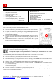
3. Locate and press the coding pushbutton on the receiver board (figure 1);
4. Put power into the receiver by keeping the coding pushbutton pressed for 3-4
sec.; the yellow led on the receiver board flashes two time per second; so
release the coding pushbutton;
5. Press any 3 keys at the same time on the transmitter within 15 seconds since it
has been switched on (also more time if it is necessary; the yellow led stop to
blink);
6. At this time, the transmitter is codified with the reveiver; check all the system
function by trying the movements of the system;
7. Close the receiver box by screwing the two screw removed at step 2.
Figure 1. Coding pushbutton
RELAY MOTOR RESETTING
The relay motor resetting is an operation to carry out in order to change its coupling with the other outputs (OUT1,
OUT2, OUT3…) from the original standard system setting.
By a standard system setting when any key is pressed on the radio control transmitter the
correspondent output and relay motor output is activated. (see “Instructions for use” in the
radio control transmitter manual).
To change therealy motor output coupling with the output requie, it is necessary to act as follows:
1. Disconnect the power to the receiver;
2. Open the receiver box, by unsrewing the 2 screws at the side of the connector;
3. Put power into the receiver;
4. Press simultaneously the coding button on the receiver board (fig. 1) and START key on the transmitter for 3-4
sec., so release the 2 keys;
5. Activate in a row, by the transmitter, the outputs that are to be coupled with the relay motor;
6. Press simultaneously the coding button on the receiver board (fig. 1) and STOP key on the transmitter for 3-4
sec., so release the 2 keys;
7. At this time the new output and relay motor coupling is recorded; check all the system function by trying the
movements of the system;
8. Close the receiver box by screwing the two screw removed at step 2.
In case any error should occur while resetting the system, it is possible to cancel the operation, by taking the power
off the system and repeating the operation.