
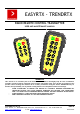
User Manual

SISTEMATICA S.p.A. Pag. 2/4
Via S. Pertini, 17 – 12030 MANTA (CN) ITALY Tel. +39 0175 255.711 r.a. – Fax +39 0175 255.715
http://www.sistematica.it e-mail: info@sistematica.it
TECHNICAL FEATURES
EASYRTX
• Manufacturer: SISTEMATICA S.p.A.
• Number of commands: da 2 a 6
• Dimension (in mm): 109 x 56 x 30
• IP protection: IP67
• Operating temperature: -20°C ÷ +70°C
• Battery supply: n°2 AAA Alkaline 1,5V cell
• Quiescent absorption: 1 µA
• Back lighted keypad
• Safetypoint
• Tilting-hand
• Buzzer
• Working distance: 100÷150 m in free fiel condition
TRENDRTX
• Manufacturer: SISTEMATICA S.p.A.
• Number of commands: da 4 a 24
• Dimension (in mm): 165 x 80 x 40
• IP protection: IP67
• Operating temprature: -20°C ÷ +70°C
• Battery supply: n°2 AA Alkaline 1,5V cell
• Quiescent absorption: 5 µA
• Back lighted keypad
• Active Safetypoint
• Tilting-hand
• Buzzer
• Working distance: 100÷150 m in free fiel condition
INSTRUCTIONS FOR USE
RADIO REMOTE CONTROL 6÷14 FUNZIONI
(EASYRTX E TRENDRTX)
RADIO REMOTE CONTROL UP TO 24 FUNZIONI
(ONLY TRENDRTX)
1. Switch on the receiver;
2. Wait for a few second (self testing);
3. Press START key to allow the system to receive the
transmission (the system stay active for n.2 minutes
after the last control has been given, after wich it
reset.. Then press START key again to restart the
system);
4. Press the required key on the trasmitter to activate
the related output on the receiver
EXAMPLE: KEY 1 → OUT1 + M.O. + EM.
↓
EXAMPLE: KEY 6 → OUT6 + M.O. + EM.
↓
EXAMPLE: KEY 14 → OUT14 + M.O. + EM.
5. Press the STOP key to inhibit the controls
reception. In this phase all the controls are reset. To
activate again the system press START.
EASYRTX TRENDRTX
1. Switch on the receiver;
2. Wait for a few second (self testing);
3. Press START key and key 1 at the same time to
enable the output on the receiver unit from 1 to 12
(I° page); press the required key on the transmitte r
to activate the related output on the receiver:
EXAMPLE: KEY 1 → OUT1 + M.O. + EM.
↓
EXAMPLE: KEY 12 → OUT12 + M.O. + EM.
4. Press START key and key 2 at the same time to
enable the output on the receiver unit from 13 to 24
(II° page); press the required key on the transmitt er
to activate the related output on the receiver:
EXAMPLE: KEY 13 → OUT13 + M.O. + EM.
↓
EXAMPLE: KEY 24 → OUT24 + M.O. + EM.
5. Press the STOP key to inhibit the controls
reception. In this phase all the controls are reset. To
activate again the system press START and key 1
or key 2 depend on output want activate.
NOTE: The 24 function transmitter is composed by 2
pages. First page enable first 12 outputs (OUT 1 ÷ OUT
12); second page enable last 12 outputs (OUT 13 ÷
OUT 24).