Network IP-Camera LN-406 Wireless Network 54g IP-Camera WL-404 Full Manual
Table of Contents 1. Introduction.....................................................................................................4 Overview..........................................................................................................4 Features.....................................................................................................4 Internet Features.........................................................................................5 Security Features........................
Administrator ID.....................................................................................37 Upgrade File...........................................................................................37 Backup Config File..................................................................................37 Restore Factory Defaults .........................................................................38 Toolbox - Status..................................................................................
1. Introduction Overview The Network Camera has an Integrated Microcomputer and a high quality CMOS digitalImage-Sensor, enabling it to display high quality live streaming video over your wired LAN, the Internet, and for the Network Camera, an 802.11g Wireless LAN. Using enhanced MPEG-4 technologies, the Network Camera is able to stream high quality video and audio directly to your PC. The high compression capabilities of MPEG-4 reduce network bandwidth requirements to amazingly low levels.
Internet Features • User-definable HTTP port number. This allows Internet Gateways to use "port mapping" so the Network Camera and a Web Server can share the same Internet IP address. • DDNS Support. In order to view video over the Internet, users must know the Internet IP address of the gateway used by the Network Camera. But if the Gateway has a dynamic IP address, DDNS (Dynamic DNS) is required. Since many existing Gateways do not support DDNS, this function is incorporated into the Network Camera.
Physical Details Front - Network Camera Lens Microphone Power LED (Green) Active LED (Green) Network LED (Green) No physical adjustment is required or possible for the lens, but you should ensure that the lens cover remain clean. The image quality is degraded if the lens cover is dirty or smudged. The built-in microphone is mounted on the front. On - Power on. Off - No power. Blinking - The Power LED will blink during start up. This will take 15 to 20 seconds. Off - Camera is not capturing video.
Rear - Network Camera Antenna SPKR out Power Input LAN port Attach the supplied antenna here. The antenna is adjustable; best results are usually obtained with the antenna positioned vertically. If required, an external speaker can be plugged in here. Connect the supplied 5V power adapter here. Do not use other power adapters; doing so may damage the camera. Use a standard LAN cable to connect your Network Camera to a 10/100BaseT hub or switch.
Package Contents The following items should be included: If any of these items are damaged or missing, please contact your dealer immediately. 1. Network Camera 2. Antenna (WL-404 only) 3. Power adapter 4. Installation CD-ROM 5.
2. Basic Setup System Requirements • To use the wired LAN interface, a standard 10/100BaseT hub or switch and network cable is required. • To use the Wireless interface on the Wireless IP Camera with MPEG4/MJPEG, other Wireless devices must be compliant with the IEEE802.11b or IEEE802.11g specifications. All Wireless stations must use compatible settings. The default Wireless settings are: Mode Infrastructure SSID Sitecom Security Disabled Channel Auto Installation - Network Camera 1.
Setup using the Windows Wizard Initial setup should be performed using the supplied Windows-based setup Wizard. This program can locate the Network Camera even if its IP address is invalid for your network. You can then configure the Network Camera with appropriate TCP/IP settings for your LAN. Subsequent administration can be performed with your Web browser, as explained in Chapter 5 - Web-based Management. Setup Procedure Insert the supplied CD-ROM into your drive.
• Select the desired Camera from the list on the left. The current settings for the selected Camera will be displayed in the table on the right. • Click Next to continue. • • You will be prompted to enter the Administrator Name and Administrator Password, as shown below. • If using the default values, enter admin for both the name and password. (Otherwise, enter the Administrator Name and Administrator Password set on the Maintenance screen.
• This screen allows you to enter a suitable Description, and set the correct Time Zone, Date, and Time. Make any desired changes, then click Next to continue. • The next screen, shown below, displays all details of the Network Camera. • Click Next if the settings are correct • Click Back to modify any incorrect values. • Click OK to confirm that you want to save the new settings. If you want to cancel your changes, click Cancel. • After clicking OK, you will see the screen below.
3. Viewing Live Video Overview After finishing setup via the Windows-based Wizard, all LAN users can view live video using Internet Explorer on Windows. Many other powerful features and options are also available: • To view multiple cameras simultaneously, or record video (either interactively or by schedule), you should install the Windows Viewing/Recording utility. Refer to Chapter 2 – Setup Procedure, and chapter 6 – Monitor utility for details on installing and using this program.
Network Camera administrator.) 6. The first time you connect to the camera, you will be prompted to install an ActiveX component (OCX or CAB file), as in the example above. You must install this ActiveX component (OCX or CAB file) in order to view the Video stream in Internet Explorer. Click the “Yes” or “Install” button to install the ActiveX component. 7. Video will start playing automatically. There may be a delay of a few seconds while the video stream is buffered.
Viewing Live Video After installing the ActiveX component, you will be able to view the live video stream in its own window, as shown below. There are a number of options available on this screen, accessed by select list, button or icon. See the table below for details. General Options These options are always available, regardless of the type of camera you are connected to. Resolution. Use this drop-down list to select the desired video size. Zoom. A digital zoom feature is available.
4. Advanced Viewing Setup Introduction This chapter describes some additional settings and options for viewing live Video: • Adjusting the video image • Controlling user access to the live video stream • Making video available from the Internet • Using the Motion Detection feature Adjusting the Video Image If necessary, the Network Camera Administrator can adjust the Video image. 1. Connect to the Web-based interface of the Network Camera. (See Chapter 5 - Webbased Management for details.) 2.
MJPEG Settings Resolution Select the desired video resolution format. The default resolution is set to 320*240. Fixed Video Select the desired fix quality. The default fix quality is set to Normal. Quality Max. Frame Select the desired Maximum bandwidth for the video stream. Note Rate that you can specify EITHER the Bandwidth OR the Frame Rate, not both. If the Bandwidth is defined, the frame rate will be adjusted as necessary to achieve the specified frame rate.
Controlling User Access to the Video Stream By default, anyone can connect to the Network Camera and view live Video at any time.If desired, you can limit access to scheduled times, and also restrict access to known users. 1. Connect to the Web-based interface of the Network Camera. (See Chapter 5 - Webbased Management for details.) 2. Select Administration, then Video Access. 3. Set the desired options for Access.
HTTP Port Configuration Normally, HTTP (Web) connections use port 80. Since the Network Camera uses HTTP, but port 80 is likely to be used by a Web Server, you can use a different port for the Network Camera. This port is called the Secondary Port. The default Secondary Port is 1024. If you prefer to use a different port number, you can specify the port number on the Network Camera's Network screen. See Chapter 5 - Web-based Management for further details on using the Network screen.
Viewing Live Video via the Internet Clients (viewers) will also need a broadband connection; dial-up connections are NOT recommended. Viewing Live Video Using your Web Browser If using your Web browser, you need to know the Internet IP address (or the Domain name) of the camera's Router/Gateway, and the correct port number. Enter the Internet address of the Router/Gateway, and its port number, in the Address (or Location) field of your Browser. Example - IP address: HTTP://203.70.212.
Motion Detection Alerts The Motion Detection feature can generate an Alert when motion is detected. The Network Camera will compare consecutive frames to detect changes caused by the movement of large objects. But the motion detector can also be triggered by: • Sudden changes in the level of available light • Movement of the camera itself. Try to avoid these situations. The motion detection feature works best in locations where there is good steady illumination, and the camera is mounted securely.
5. Web-based Management Introduction The Network Camera can be configured using your Web Browser. The Network Camera must have an IP address which is compatible with your PC. The recommended method to ensure this is to use the supplied Windows-based Wizard, as described in Chapter 2 - Basic Setup.
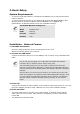
Basic Settings – System After clicking Basic Settings on the main menu, you will be asked for your username and password. Enter “admin” as username, and “admin” as password. After logging in, you'll see a screen like the example below. System Settings Device ID This displays the name for the Network Camera. Description This field is used for entering a description, such as the location of the Network Camera.
LED Operation Enable this if you want to use this function. Basic Settings - Network This screen is displayed when the Network menu option is clicked. Network Obtain an IP Address Automatically Use the following IP Address Obtain DNS server address automatically Use the following DNS server address Secondary Port If selected, the Network Camera will obtain its IP address and related information from a DHCP Server. Only select this option if your LAN has a DHCP Server.
http://192.168.1.100:1024 The RTSP (Real Time Streaming Protocol), a standard for connected client(s) to control streaming data (MPEG-4) over the World Wide Web. Enter the RTSP Port number (between 1024 and 65535) in the field provided. The default RTSP Port is 554. The RTP (Real Time Transport Protocol), an Internet protocol for transmitting real-time data such as audio and video. Max RTP Data Packet field will let users limit the size of the file. Enter the desired value between 400 and 1400.
Basic Settings - Wireless (WL-404 only) This screen is displayed when the Wireless menu option is clicked. Wireless Network Network Type This determines the type of wireless communication used by the Network Camera. • If you have an Access Point, select Infrastructure. • SSID Domain Channel No. Security Security System WEP Authentication Type Otherwise, select Ad-hoc. This must match the value used by other devices on your wireless LAN. Note! The SSID is case sensitive.
WEP Encryption Passphrase WEP Keys Check your wireless card's documentation to see what method to use. Note: In Infrastructure mode, either setting will normally work, since most Access Points can use both methods.
Basic Settings - DDNS Many internet connections use a "Dynamic IP address", where the Internet IP address is allocated whenever the Internet connection is established.This means that other Internet users don't know the IP address, so can't establish a connection. DDNS is designed to solve this problem, as follows: • You must register for the DDNS service with a DDNS service provider. The DDNS Service provider will allocate a Domain Name to you upon request.
Video & Audio - Basic This screen is displayed when the Video & Audio option is clicked. MPEG-4 Settings Resolution Select the desired video resolution format. The default resolution is set to 320*240. Video Quality • Constant Bit Rate: Select the desired bit rate. The default is set Control to 1.2 Mbps. • Max. Frame Rate Fixed Quality: Select the desired option. The default fix quality is set to Normal. Select the desired Maximum bandwidth for the video stream.
Rate Access Code Enter the code for accessing the live video from camera through cell phone connection. Video Adjustments Power Line Select the power line frequency (50Hz or 60Hz) used in your region, Frequency to improve the picture quality under florescent lighting. White Balance Select the desired option to match the current environment and lighting. Brightness If necessary, you can adjust the brightness to obtain a better image.
The camera administrator must use the "User Database" menu option to create the desired users. Video Access Enable Scheduled Video Access • If enabled - Camera is available during the scheduled periods, and unavailable at other times. If this option is selected, you need to define a schedule. If no schedule is defined, this option is always disabled. • If disabled – The option will remain disabled until you enable it.
have 2 names which differ only by case. User Password Confirm Password Add Button Clear Button The password for this user. Re-enter the password for the user, to ensure it is correct. Click this button to add a new user, using the data shown on screen. Use this button to clear the input fields, ready to add a new user. Event - Motion Detection This screen is displayed when the Motion Detection option on the Event menu is clicked.
Event - E-Mail This screen is displayed when the E-Mail option on the Event menu is clicked. . Primary/Secondary SMTP Server SMTP Server Enter the address of the SMTP (Simple Mail Transport Protocol) Address Server to be used to send E-Mail. Authentication Select the desired Authentication type for the SMTP Server. SMTP Login Enter your login name for the SMTP Server. name SMTP Enter your password for the SMTP Server. Password POP server Enter the name for the POP Server.
Event - FTP This screen is displayed when the FTP option on the Event menu is clicked. Primary/Secondary FTP FTP Server Enter the address of the FTP Server. Port Enter the Port of the FTP Server to be connected. Login name Enter your login name for the FTP Server. Password Enter your password for the FTP Server. Enable Check the box to enable the Passive mode feature of the FTP. Passive Mode File Path Enter the file path/name of the FTP.
Event - HTTP This screen is displayed when the HTTP option on the Event menu is clicked. HTTP Notification Enable Enable this checkbox to use the HTTP Notification. URL Enter the URL of your HTTP notification server. Proxy Server Specify the proxy server name in the provided field if the camera Name needs to pass through a Proxy Server to do the HTTP notification. Port Number Enter the port number for the proxy server. Method Select the desired method of form data encoding.
Event - Trigger This screen is displayed when the Event Trigger option on the Event menu is clicked. Event Schedule Schedule List The Event Schedule shows all of the event types currently configured in the Network Camera, along with various information about their configuration, as listed below: • Name - the descriptive event name set by the user.
the JPEG image depends on this setting, and also the file size and degree of compression. • Video: Video Format - Select the desired type for the video file. Pre/Post Capture - Select the desired length. The size of the file depends on this setting, and also the Video size and degree of compression. Toolbox - Basic . Administrator Login Administrator ID Administrator Password Verify Password Enter the name for the Administrator here.
Restore Factory Defaults Restart Camera Click Defaults button to reloads all default settings on the camera. Click Restart button to restarts the camera. Toolbox - Status System Device Name Description F/W version Network MAC Address IP Address Network Mask Gateway This shows the name of the Network Camera. This shows the description of the Network Camera, such as location. The version of the current firmware installed. The current IP address of the Network Camera. The IP Address of the Network Camera.
Frame Rate Buttons Refresh This displays the frame rate of the video stream. Update the log and any other data on screen. Log Screen This screen displays a log of system activity. Log System Log Enable Syslog Service Syslog Server Address Refresh Button Clear Log This is a log of system activity. Check the box to enable the System Log Server feature. Enter the address of the Syslog Server. Click this to update the data shown on screen. Click this button to restart the log.
6. Windows Monitor/Playback/Recorder utility The recommended method to view video is to use the supplied Windows Viewing/Recording utility. This utility also allows you to record the video streams, either interactively or using a schedule. System Tray Icon When started, the program will create an icon in the Windows system tray on the taskbar, as shown below. You can right click the icon and it will provides a menu which allows you to view program details, view the main screen, or terminate the program.
2. Select the desired Channel number in the left (No.) column. 3. There are 2 radio buttons, for LAN or Internet. The default is LAN. See the following section for details of the Internet option. • The LAN panel, on the left, displays all Network Camera found on your LAN. This list can be updated by clicking the Refresh button. • The Camera Data panel, on the right, displays the data for the selected camera. 4. To associate a camera with the current Channel: • • • • Select a camera in the list on the left.
You can add the same Camera twice, once for the LAN (using the LAN IP address), and again for the Internet (using the Internet IP address). This will allow viewing the camera whether you are on the same LAN as the camera or in a remote location. Adding Cameras on the Internet If the Network Camera you wish to add is not on your LAN, but is available via the Internet, click the Internet button. You will see a screen like the example below. To associate a camera with the current Channel: 1.
and password before being allowed to view the live video. • If the Camera Administrator has not enabled this option, the Login fields can be left blank. • Stream Type Setup Camera Pages Enable Trigger Event Otherwise, you must enter the username and password allocated to you by the Camera Administrator. Select the desired video stream type. There might be either MPEG4 or Motion-JPG streaming type.
Play. Use this to re-start viewing, after using the Stop or Pause button. Pause. Use this to temporarily stop the connection to the camera Stop. This will terminate the connection to the camera, halting both the viewing and the recording (if in progress). Record. Click this to start recording the current video stream. While recording, this button will be blue. To stop recording, click the Stop button. Snapshot. Click this to take a single JPEG "snapshot" image of the current video. Zoom Camera.
If necessary, change these settings to suit your environment. Local ID. This is the name you gave to this camera. This field must be entered. Interval. Decide which days you want the Camera to record. Select the appropriate Interval from the drop-down list. Start Date. Select the date you want the recording begin. Start Time. Select the time you want the recording begin. Duration. Select how ling you want the recording to be.
Preferences This screen is displayed after clicking the Preferences tab on the Setup screen. If necessary, change these settings to suit your environment. Data - Preferences Recording Paths Recording This is the Drive and Folder on your PC where recorded files will be placed. You need a drive which has large amounts (Gigabytes) of free space. Click the Browse button to select the drive and folder. Note that file names are automatically assigned, using the date and time.
if the space is not enough for recording. • Initial Settings Launch this utility when Windows started Proxy Server Enable proxy Stop Recording. If the disk space limit is reached, no further recording is done. Check this to have this utility start when Windows starts. If enabled, click the Proxy Settings button to configure the settings. Using Playback To access the saved files of the Camera, click Playback button in the Main screen, then you will see the following screen.
Stop. This will terminate the connection to the camera, halting both the viewing and the recording (if in progress). Snapshot. Click this to take a single JPEG "snapshot" image of the current video. Zoom In. To zoom in on a section of the window, click this icon. Zoom Out. To zoom out on a section of the window, click this icon. Print. Click this to print the current video stream. Playback Speed. To play a recorded file, select the desired speed. Audio Control.
Appendix A: Model Dimensions Operating Temperature Storage Temperature Network Protocols: Network Interface: Wireless interface LEDs Power Adapter Lens Network Camera - Specifications Network Camera 90mm (W) * 35mm (H) * 90mm (D) 0 °C to 40 °C 0 °C to 40 °C TCP/IP, DHCP, SMTP, NTP, HTTP, FTP, NTP, RTP, RTSP, UPnP (Discovery only) 1 Ethernet 10/100BaseT (RJ45) LAN connection IEEE 802.11b/802.
CE Approvals The Network Camera and the Ethernet Network Camera meet the guidelines of the European Union and comply with the 99/5/EEC and RTTE 99/5EG directives, including the following standards: • EN60950 • EN300 328-2 • EN301 489-1 • EN301 489-17 This is a Class B product. In a domestic environment this product may cause radio interference in which case the user may be required to take adequate measures.
Copyright Notice Many software components are covered by the GNU GPL (General Public License). Some are covered by other Licenses as listed in the table below. Details of each applicable license are contained in the following section. No Warranty THIS SOFTWARE IS PROVIDED BY THE AUTHOR AND CONTRIBUTORS ``AS IS'' AND ANY EXPRESS OR IMPLIED WARRANTIES, INCLUDING, BUT NOT LIMITED TO, THE IMPLIED WARRANTIES OF MERCHANTABILITY AND FITNESS FOR A PARTICULAR PURPOSE ARE DISCLAIMED.
2. Redistributions in binary form must reproduce the above copyright notice, this list of conditions and the following disclaimer in the documentation and/or other materials provided with the distribution. THIS SOFTWARE IS PROVIDED BY THE AUTHOR AND CONTRIBUTORS ``AS IS'' AND ANY EXPRESS OR IMPLIED WARRANTIES, INCLUDING, BUT NOT LIMITED TO, THE IMPLIED WARRANTIES OF MERCHANTABILITY AND FITNESS FOR A PARTICULAR PURPOSE ARE DISCLAIMED.
cron license Copyright (c) 1989 The Regents of the University of California. All rights reserved. This code is derived from software contributed to Berkeley by Paul Vixie.
effect making the program proprietary. To prevent this, we have made it clear that any patent must be licensed for everyone's free use or not licensed at all. The precise terms and conditions for copying, distribution and modification follow. GNU GENERAL PUBLIC LICENSE Terms And Conditions For Copying, Distribution And Modification 0.
3.
It is not the purpose of this section to induce you to infringe any patents or other property right claims or to contest validity of any such claims; this section has the sole purpose of protecting the integrity of the free software distribution system, which is implemented by public license practices.
Lesser GNU General Public License GNU LESSER GENERAL PUBLIC LICENSE Version 2.1, February 1999 Copyright (C) 1991, 1999 Free Software Foundation, Inc. 51 Franklin St, Fifth Floor, Boston, MA 02110-1301 USA Everyone is permitted to copy and distribute verbatim copies of this license document, but changing it is not allowed. [This is the first released version of the Lesser GPL. It also counts as the successor of the GNU Library Public License, version 2, hence the version number 2.1.
Finally, software patents pose a constant threat to the existence of any free program. We wish to make sure that a company cannot effectively restrict the users of a free program by obtaining a restrictive license from a patent holder. Therefore, we insist that any patent license obtained for a version of the library must be consistent with the full freedom of use specified in this license. Most GNU software, including some libraries, is covered by the ordinary GNU General Public License.
another language. (Hereinafter, translation is included without limitation in the term "modification".) "Source code" for a work means the preferred form of the work for making modifications to it. For a library, complete source code means all the source code for all modules it contains, plus any associated interface definition files, plus the scripts used to control compilation and installation of the library.
General Public License has appeared, then you can specify that version instead if you wish.) Do not make any other change in these notices. Once this change is made in a given copy, it is irreversible for that copy, so the ordinary GNU General Public License applies to all subsequent copies and derivative works made from that copy. This option is useful when you wish to copy part of the code of the Library into a program that is not a library. 4.
user who changes the contents of definitions files in the Library will not necessarily be able to recompile the application to use the modified definitions.) b) Use a suitable shared library mechanism for linking with the Library.
11. If, as a consequence of a court judgment or allegation of patent infringement or for any other reason (not limited to patent issues), conditions are imposed on you (whether by court order, agreement or otherwise) that contradict the conditions of this License, they do not excuse you from the conditions of this License.
16.
Appendix B: Streaming Video/Audio Solution Overview Streaming video is a sequence of "moving images" that are sent in compressed form over the Internet and displayed by the viewer as they arrive. With streaming, a Web user does not have to wait to download a large file before seeing the video or hearing the sound. Instead, the media is sent in a continuous stream and is played as it arrives.