
User Guide
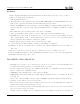


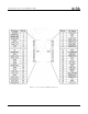
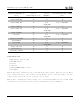
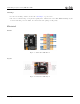
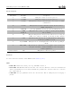
Table Of Contents

Sixfab Raspberry Pi 3G-4G/LTE Base HAT
Pin Descriptions
Pin Number Pin Name Description
2 5V PWR This pin is connected to the 5V power net
4 5V PWR This pin is connected to the 5V power net
8 PCI RX This pin functions as the serial data input to the module for UART
communication
10 PCI TX This pin functions as the serial data output from the module for
UART communication
13 USER LED It is a programmable user-led can control from Raspberry Pi
15 USER
BUTTON
This push button connected to Raspberry Pi and pulled up HIGH
state by default.
31 RI
This pin is Ring indicator functions as the indication for receiving call
or SMS, can be calibrated to HIGH or LOW using the AT commands
33 DTR When the module is in sleep mode, DTR pin allows to wake up the
module up by pulling it to LOW
35
W_DISABLE
This pin is used to turn Airplane Mode on the module, by pulling it
HIGH
37
HAT_PWR_OFF
The pin is used to shutdown the power regulator of the board and cut
the power of module by driving it HIGH state, can be used power
sensitive applications
6,9,14,25,30,34,39 GND This pins are connected to ground
Schematic
You can download the schematic of Base HAT from this Github repository.
LEDs
• PWR LED: When the module is powered up, this RED led turns on.
• SGNL LED:
This BLUE led indicates the status of the connection. When the connection is established and
data is being transmitted/received, this led will blink at special intervals. Otherwise, if there is no connection,
the led will remain off.
• USER LED:
It is a programmable user-led can control from the GPIO27 of Raspberry Pi for debugging or
just fun.
Copyright © 2019, Sixfab Inc 10