총무팀 / 사원 테스트용 / 10.1.10.134 / 2010- 02- 05 17:27 / 이 문서는 보안문서로서 외부 반출을 금합니다. SMR-AI231 User Manual SK telesys SKTSP-CP-06-03 A4(210X297) 총무팀 / 사원 테스트용 / 10.1.10.134 / 2010- 02- 05 17:27 / 이 문서는 보안문서로서 외부 반출을 금합니다.
총무팀 / 사원 테스트용 / 10.1.10.134 / 2010- 02- 05 17:27 / 이 문서는 보안문서로서 외부 반출을 금합니다. SMR-AI231 Contents 1 INTRODUCTION................................................................................................................. 5 1.1 FCC compliance ........................................................................................................................ 5 1.2 Important safety information ............................................................................................... 6 1.2.
총무팀 / 사원 테스트용 / 10.1.10.134 / 2010- 02- 05 17:27 / 이 문서는 보안문서로서 외부 반출을 금합니다. SMR-AI231 Figures Figure 1. SMR-AI231 Block diagram ................................................................................... 11 Figure 2. Top side of the SMR-AI231 ................................................................................... 12 Figure 3. The Body-Mount-Bracket change process ........................................................... 16 Figure 4. The Wall-Mount-Bracket installation .............
총무팀 / 사원 테스트용 / 10.1.10.134 / 2010- 02- 05 17:27 / 이 문서는 보안문서로서 외부 반출을 금합니다. SMR-AI231 4 총무팀 / 사원 테스트용 / 10.1.10.134 / 2010- 02- 05 17:27 / 이 문서는 보안문서로서 외부 반출을 금합니다.
총무팀 / 사원 테스트용 / 10.1.10.134 / 2010- 02- 05 17:27 / 이 문서는 보안문서로서 외부 반출을 금합니다. SMR-AI231 1 Introduction This operating instructions manual provides all the information you need for connection, setup and installation as well as important instructions for operation and maintenance. Please read this information before putting the SMR-AI231 into installation and operation and keep this operating instruction manual accessible in the immediate vicinity of the product.
총무팀 / 사원 테스트용 / 10.1.10.134 / 2010- 02- 05 17:27 / 이 문서는 보안문서로서 외부 반출을 금합니다. SMR-AI231 measures. Reorient or relocate the receiving antenna. Increase the separation between the equipment and receiver. Connect the equipment into an outlet on a circuit different from that to which the receiver is connected. Consult the dealer or an experienced Radio/TV technician for help.
총무팀 / 사원 테스트용 / 10.1.10.134 / 2010- 02- 05 17:27 / 이 문서는 보안문서로서 외부 반출을 금합니다. SMR-AI231 1.2.2 Warning Do not use the product in a dusty or humid environment It may cause a short circuit or a build up heat, result in fire or electric shock. Protect against static electricity An electrostatic discharge may damage components of this product. Do not directly touch any of the connector or component surfaces Static electricity can be generated on clothing and people.
총무팀 / 사원 테스트용 / 10.1.10.134 / 2010- 02- 05 17:27 / 이 문서는 보안문서로서 외부 반출을 금합니다. SMR-AI231 Do not disassemble Do not remove the cover or modify. For hope internal inspection or repair. Please contact your system integrator directly. Do not use the product in a damaged condition Do not drop the product and use the product with its cover, antenna and AC adapter broken. It may result in fire or malfunction of this product.
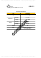
총무팀 / 사원 테스트용 / 10.1.10.134 / 2010- 02- 05 17:27 / 이 문서는 보안문서로서 외부 반출을 금합니다. SMR-AI231 1.3 Physical and Environment Table 1. Physical Specification Item Description Weight Under 1.0kg Operating 0°C ~50°C Storage -10°C ~60°C Operating 20%~80% Storage 10%~85% Temperature Humidity Antenna SMA PoE(Power-over-Ethernet) or Power 5.3 V AC/DC Adaptor 9 총무팀 / 사원 테스트용 / 10.1.10.134 / 2010- 02- 05 17:27 / 이 문서는 보안문서로서 외부 반출을 금합니다.
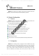
총무팀 / 사원 테스트용 / 10.1.10.134 / 2010- 02- 05 17:27 / 이 문서는 보안문서로서 외부 반출을 금합니다. SMR-AI231 2 SMR-AI231 Features SMR-AI231 is composed of the substance, antennas and accessories. Prior to the installation, the element lists below should be identified by operators 2.1 Product Configuration 2.1.1 Features SMR-AI231 provide a high speed, which means users can be connected to the internet and is designed to be extension for the service coverage.
총무팀 / 사원 테스트용 / 10.1.10.134 / 2010- 02- 05 17:27 / 이 문서는 보안문서로서 외부 반출을 금합니다. SMR-AI231 according to your plan. The power ON/OFF could be activated by the slide switch. There are omni-directional types as antennas. The Product has a 8-bit dip switch to set up the its ID. You can take a look into the block diagram of SMR-AI231 as below: Figure 1. SMR-AI231 Block diagram 11 총무팀 / 사원 테스트용 / 10.1.10.134 / 2010- 02- 05 17:27 / 이 문서는 보안문서로서 외부 반출을 금합니다.
총무팀 / 사원 테스트용 / 10.1.10.134 / 2010- 02- 05 17:27 / 이 문서는 보안문서로서 외부 반출을 금합니다. SMR-AI231 2.2 Indicator and operating elements Figure 2. Top side of the SMR-AI231 • ANT-A, ANT-B: Omni Antenna. • Power Switch: The power switch activates ON or OFF for power. The switch is moving to left side for power on and moving to right side for power off. • DC Power Jack: The power cable is connected into the power jack in order to activate power on for the SMR-AI231.
총무팀 / 사원 테스트용 / 10.1.10.134 / 2010- 02- 05 17:27 / 이 문서는 보안문서로서 외부 반출을 금합니다. SMR-AI231 3 Installation Guide SK Telesys is not responsible for product damage incurred during shipment. You must make claims directly with the carrier. obvious signs of damage. Inspect your shipment carefully for If the shipment appears damaged, retain the original boxes and packing material for inspection by the carrier. Contact your carrier immediately. 3.
총무팀 / 사원 테스트용 / 10.1.10.134 / 2010- 02- 05 17:27 / 이 문서는 보안문서로서 외부 반출을 금합니다. SMR-AI231 Table 2. Element List Item Description Count(EA) SMR-AI231 1 Omni Antenna 2 AC/DC Adapter 1 Body-Mount-Bracket 1 Wall-Mount-Bracket 1 4Ø Screw 3 5Ø Screw 4 User manual 1 NOTE: The unauthorized power adapter can make a problem 14 총무팀 / 사원 테스트용 / 10.1.10.134 / 2010- 02- 05 17:27 / 이 문서는 보안문서로서 외부 반출을 금합니다.
총무팀 / 사원 테스트용 / 10.1.10.134 / 2010- 02- 05 17:27 / 이 문서는 보안문서로서 외부 반출을 금합니다. SMR-AI231 3.3 Choose the best location Select the installation location that is based on the surrounding environment and Cell planning. After you finish the installation, following these directions, it should not interfere with your decor. You must use an enclosed Wall-Mount-Bracket to fix the SMR-AI231. Therefore, the installation site has to meet the following recommendation. 1.
총무팀 / 사원 테스트용 / 10.1.10.134 / 2010- 02- 05 17:27 / 이 문서는 보안문서로서 외부 반출을 금합니다. SMR SMR-AI231 3. Turn three 4Ø screws in a clockwise direction to fix the SMR R-AI231(ⓒ) 4. Refer to the figure below. Figure 3. The Body-Mount-Bracket change process 3.5 The Wall-Mount Mount-Bracket Installation The Wall-Mount-Bracket racket should be installed tightly to the wall. In order to secure the wall-mount-bracket, bracket, you can use the enclosed four 5Ø screws. 1.
총무팀 / 사원 테스트용 / 10.1.10.134 / 2010- 02- 05 17:27 / 이 문서는 보안문서로서 외부 반출을 금합니다. SMR SMR-AI231 Figure 4. The Wall-Mount-Bracket installation 3.6 The SMR-AI231 AI231 Mounting After the Wall-Mount Mount-Bracket installing,, you should connect the enclosed 2 omni-antenna antenna to the port on the side of the product as the figure below. The left and right antenna is the same. Figure 5. Omni Antenna assembling 17 총무팀 / 사원 테스트용 / 10.1.10.134 / 2010- 02- 05 17:27 / 이 문서는 보안문서로서 외부 반출을 금합니다.
총무팀 / 사원 테스트용 / 10.1.10.134 / 2010- 02- 05 17:27 / 이 문서는 보안문서로서 외부 반출을 금합니다. SMR SMR-AI231 And you need to determine d how power is supplied. (PoE(Power-Over-Ethernet) (PoE(Power or AC/DC Adaptor) If you have used the AC/DC adapter, you should connect the enclosed AC/DC adapter to a PWR jack on the top of the SMR-AI231. But if you use the PoE(Power-Over- Ethernet) switch, you will not need the AC/DC adapter. And then you can connect the UTP cable to the ETH port.
총무팀 / 사원 테스트용 / 10.1.10.134 / 2010- 02- 05 17:27 / 이 문서는 보안문서로서 외부 반출을 금합니다. SMR-AI231 3.7 Power on the SMR-AI231 After mounting the product, you can turn on the switch on the top of the SMR-AI231. The status of LEDs should be checked with a power supply. 1. The PWR LED should have a green light on when the Product power is on. 2. Make sure the green light stays on after the RUN LED finishes blinking initially. 3. Make sure the green light comes on within 5 minutes after the STS LED has flashed green.
총무팀 / 사원 테스트용 / 10.1.10.134 / 2010- 02- 05 17:27 / 이 문서는 보안문서로서 외부 반출을 금합니다. SMR-AI231 4 Maintenance The description in this chapter contains service and information for abnormal case of SMR-AI231. To solve the problem directly that effort has to establish the cause is needed. Basically, the SMR-AI231 supports several functions to indicate problem kinds. 4.1 Diagnostic for LED There are three LEDs on the front panel that indicates the status of the SMR-AI231: Power, Run and Status Figure 7.
총무팀 / 사원 테스트용 / 10.1.10.134 / 2010- 02- 05 17:27 / 이 문서는 보안문서로서 외부 반출을 금합니다. SMR-AI231 4.1.1 Power LED The power LED indicates whether or not the SMR-AI231 is powered on and operating normally. This is located on the leftmost side of three lights Table 3. Power LED Power LED Description Green The SMR-AI231 is powered and operating normally. (Power Normal) Red An error occurred. The SMR-AI231 is not currently functional. (Power Fail) OFF The SMR-AI231 is not getting from power source.
총무팀 / 사원 테스트용 / 10.1.10.134 / 2010- 02- 05 17:27 / 이 문서는 보안문서로서 외부 반출을 금합니다. SMR-AI231 ON The SMR-AI231 is working normally and locked from reference clock. (Normal or Clock Lock) Red The SMR-AI231 is restarting by reset OFF The SMR-AI231 is working abnormally and power off. (Abnormal or Power Off NOTE: DO NOT unplug the SMR-AI231 when the green LED is flashing on the RUN LED. 4.1.3 Status LED The status LED indicates the status of the SMR-AI231 and IEEE1588 slave module.
총무팀 / 사원 테스트용 / 10.1.10.134 / 2010- 02- 05 17:27 / 이 문서는 보안문서로서 외부 반출을 금합니다. SMR-AI231 5 Supplement Document 5.1 Technical Specification The following table illustrates the specification of Sprint AP. Table 6. The SMR-AI231 Specification Index Specification Frequency 2305MHz ~ 2315MHz, 2350MHz ~ 2360MHz Bandwidth 5MHz, Max. Output Power 10MHz 20dBm (17dBm/Ant.) Power over Ethernet (PoE) based on IEEE802.3 or Input Power 5.
총무팀 / 사원 테스트용 / 10.1.10.134 / 2010- 02- 05 17:27 / 이 문서는 보안문서로서 외부 반출을 금합니다. SMR-AI231 5.2 Dimensions Not include bracket and antennas. Figure 8. Dimensions of the SMR-AI231 5.3 ID Switch The ID switch indicates the ID of the SMR-AI23 and ID is set to the hexadecimal. ID switch is consisted of 8-bits dip switch. The relationship between hexadecimal and decimal is in the following table. 24 총무팀 / 사원 테스트용 / 10.1.10.134 / 2010- 02- 05 17:27 / 이 문서는 보안문서로서 외부 반출을 금합니다.
총무팀 / 사원 테스트용 / 10.1.10.134 / 2010- 02- 05 17:27 / 이 문서는 보안문서로서 외부 반출을 금합니다. SMR-AI231 Table 7. The SMR-AI231 ID setting Hexadecimal Decimal Weighted value 0 0 1 1 1 2 2 2 3 3 1, 2 4 4 4 5 5 1, 4 6 6 2, 4 7 7 1, 2, 4 8 8 8 9 9 1, 8 A 10 2, 8 B 11 1, 2, 8 C 12 4, 8 D 13 1, 4, 8 E 14 2, 4, 8 F 15 1, 2, 4, 8 You need to check the weighted value in the table above to set the specified ID. And then you switch on the corresponding number in the table below.
총무팀 / 사원 테스트용 / 10.1.10.134 / 2010- 02- 05 17:27 / 이 문서는 보안문서로서 외부 반출을 금합니다. SMR SMR-AI231 The he hexadecimal number C is equal to 12 in decimal. And nd the weighted value of C is 4 and 8. So you should turn on the fifth and sixth switch. Figure 9. The SMR-AI231 ID Switch Table 8. Digit Value of ID Switch Digit First digit Second econd digit ID Switch witch Number 1 2 3 4 5 6 7 8 Weighted eighted value 8 4 2 1 8 4 2 1 26 총무팀 / 사원 테스트용 / 10.1.10.