Cat. No. 877-90 Operating Instructions SKC Inc. 863 Valley View Road Eighty Four, PA 15330 USA Tel: 724-941-9701 e-mail: skctech@skcinc.
Table of Contents Introduction ................................................................................................................ 1 DataTrac Setup .......................................................................................................... 2 SKC DataTrac Pump Manager Window .................................................................... 5 SKC Real Time Monitor Window ............................................................................... 6 SKC Pump Scheduler Window .
Introduction Introduction — DataTrac for Pocket Pump® Software Cat. No.
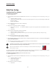
DataTrac Setup DataTrac Setup Installing DataTrac Software Installation of New Software 1. Close all applications. 2. Insert DataTrac Software CD into CD-ROM drive. The CD is set up to autoplay. If it does not autoplay on your PC, go to Step 2a. a. Click Start button on tool bar. b. Click on My Computer. (Note: In some cases, the My Computer icon may be on the desktop; double-click the icon to open.) c. Double-click CD Drive. 3. The InstallShield (IS) Welcome window will display. a. Click Next. 4.
DataTrac Setup 4. The IS Program Maintenance window will display. Three options will appear: • Modify - used to change settings after installation • Repair - used to update previously installed software • Remove - used to remove the previously installed version of the software from the hard drive (SKC recommended). a. Click Remove. b. Click Next. c. The IS Remove the Program window will display. d. Click Remove. e. The IS Uninstalling DataTrac for Pocket Pump window will display. f.
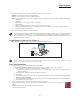
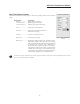
DataTrac Setup 5. If connection is successful, the Pocket Pump Connection window will display a shaking hands icon (Figure 2A). Proceed to Step 6. If connection is unsuccessful, an error window will display (see box and Figure 2B on page 5). Figure 2. Connection window Figure 2A. Successful pump-PC communication Successive Connections 1. 2. 3. 4. 5. Connect the pump to a PC using the DataTrac adapter cable. Activate the pump LCD by pressing any button on the pump keypad.
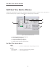
SKC DataTrac Pump Manager Window SKC DataTrac Pump Manager Window The SKC DataTrac Pump Manager window (Figure 3) is the first window that opens in DataTrac. All other windows are accessible from this main window. Figure 3. SKC DataTrac Pump Manager Window SKC DataTrac Pump Manager Window Menus File Menu Exit.................................exits the program and returns to Windows View Menu Pump Scheduler ..........opens the SKC Pump Scheduler window Sample Sheet ................
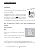
SKC Real Time Monitor Window SKC Real Time Monitor Window The SKC Real Time Monitor window (Figure 4) directly controls the pump, allows calibration of flow rate, displays a real time readout of pump operations, and displays the connected pump’s serial number. E B C A D Figure 4. Real Time Monitor Window A. B. C. D. E.
SKC Real Time Monitor Window Real Time Monitor Display The Real Time Monitor display (Figure 5) shows the operating status of the connected pump. Monitor Display Cell Readout Mode .............................RUN: pump in run state (Constant Flow or HOLD: pump in hold state Constant Pressure) FAULT: pump in flow fault state Flow...............................current flow rate in mL/min Pressure ........................back pressure in inches (ins) H2O, or millimeters (mm) Hg Volume ........................
SKC Real Time Monitor Window Flow Calibrate The Flow Calibrate buttons (Figure 6) allow calibration of the flow rate displayed on the pump LCD to the flow rate displayed on a primary standard calibrator. The Approx Correction (approximate correction) is the difference between the flow rate displayed on the pump and the flow rate displayed on the calibrator. When a pump is connected to a calibrator the flow rate is determined by the calibrator display and not the pump display.
SKC Real Time Monitor Window Temperatures Display The Temperatures display (Figure 7) shows the temperature data of the air entering the connected Pocket Pump. Temperatures Display Cell Readout Min ........................................minimum air temperature during the program run Max ........................................maximum air temperature during the program run TWA.......................................time-weighted average of all air temperatures Ambient ................................
SKC Pump Scheduler Window SKC Pump Scheduler Window The SKC Pump Scheduler window (Figure 9) is the DataTrac programming window. In this window, programs can be created, sent to a pump, saved to a PC, loaded from a PC or a pump, and printed. B G H A F I C D E Figure 9. Pump Scheduler Window A. B. C. D. E. F. G. H. I.
SKC Pump Scheduler Window Pump Scheduler Menus File Menu Open ......................opens a pump program previously stored to a PC Save .......................saves a pump program (.pgm) to a PC Print ........................ prints the pump program schedule displayed on the screen Exit.........................exits the Pump Scheduler window and returns to the SKC DataTrac Pump Manager window View Menu Pump Settings ..............opens the SKC Pump Program Settings window Clock Resolution .........
SKC Pump Scheduler Window Programming Buttons The Programming buttons (Figure 12) are used to erase a program from the Program Edit Bar, insert programs into the Pump Program Scheduler, write programs to the pump, and read programs from the pump. Figure 12. Programming Buttons Button Function Clr ..................................erases the program in the Program Edit Bar +Day ..............................adds one day to the program dates in the Program Edit Bar Insert .............................
SKC Pump Scheduler Window Edit a Program To edit a program displayed in the Pump Program Scheduler, click twice on it. This will remove it from the Pump Program Scheduler and place it in the Program Edit Bar. Any program already in the Program Edit Bar will be erased. FromPump Button To display a Pump Program Schedule from a previously programmed pump, click once on the FromPump button (Figure 12).
SKC Pump Scheduler Window Constant Pressure Window The Set Constant Pressure window (Figure 17) allows the user to select the constant pressure using the numbered pressure buttons. This window is only available when the pump is in Constant Pressure mode. Set Constant Pressure To set the constant pressure, click once on the desired constant pressure button. The new constant pressure will appear in the display cell.
SKC Pump Scheduler Window Time Bump Buttons The Time Bump buttons (Figure 24) add/subtract the selected time intervals to/from all program Start and Stop times in the Pump Program Scheduler. Time Interval To select the time interval, click once on a time interval button. Minus Button To subtract the interval from all programs, click once on the - button. Plus Button To add the interval to all programs, click once on the + button. Figure 24.
SKC Pump Program Settings Window SKC Pump Program Settings Window The SKC Pump Program Settings window (Figure 27) allows the user to select run time options. The run time options include User Lock Out, Temperature units (F or C), Pressure units (inches H2O or mm Hg), Reset Volume/Time, Reset Minimum and Maximum temperatures, and Clear History. The run time options take effect when the pump program is sent to the pump from the Pump Program Scheduler window. Figure 27.
Example Program Example Program This example program demonstrates how to use the Pump Program Scheduler window to set a program. A sampling operation requires the pump to sample at a constant flow of 100 mL/min from 8:00 AM to 4:00 PM daily for one work week. Enter the parameters as follows: Clear Previous History/Schedule In the SKC Pump Scheduler window, go to the Tools menu and select Clear History (if desired); this will erase the history from the history display and the pump’s memory.
Example Program Add extra days to the program schedule Click once on the +Day button. This will add 1 day to the Start Date and Stop Date in the Program Edit Bar. Click once on Insert to place the program into the Pump Program Scheduler. Repeat the procedure to add an additional day to the Pump Program Scheduler until each day of the week has been entered. Set the desired Run Time Options Go to the View menu and select Pump Settings. Click on the desired options (see page 16).
SKC Pump History Window SKC Pump History Window The SKC Pump History window (Figure 28) displays the record of all operations performed by the pump. Up to 50 histories may be stored in pump memory. This window also allows the user to save pump history to a PC or to print the history. SKC Pump History Menus File Menu Figure 28. SKC Pump History Window Save ...................saves a history file (.hst) to a PC Print ...................prints the current history Exit ....................
SKC Pump History Window History Display The SKC Pump History display (Figure 29) shows the record or history of all operations performed by the pump. A history will remain on screen and in the pump memory until it is cleared. A history includes the following data: Readout State of the Pump Flow.......................pump in constant flow CP ..........................pump in constant back pressure Hold ......................pump in hold Flow Fault.............
Pump Archive History Window SKC Pump Archive History Window The SKC Pump Archive History window loads and displays a pump history file (.hst) saved to a PC. This window is empty until a history file is opened from the File menu. Pump Archive History Menus File Menu Open ..................opens a saved history file (.hst) Print ...................prints the displayed history file Exit.....................
Reports Reports DataTrac allows reports and worker exposure profiles (combined snapshots and history files) to be printed as reports from the SKC Sample Sheet Setup window (Figure 31). SKC Sample Sheet Setup Window The SKC Sample Sheet Setup window (Figure 31) saves setup data pertaining to the sample run. All data displayed on the screen may be printed or saved as a setup file or user selected data may be saved as a template file. Figure 31.
Reports Template Files The SKC Sample Sheet Setup window may also be saved to a PC as a template file (.tpl). A template file reduces the need to repeatedly type data that rarely changes. A template file contains only the information included in the data cells that have an active checkbox (the small square button before the data cell as shown in Figure 32). To activate a checkbox, click once on it. Figure 32.
Reports Example of a Pocket Pump Worker Exposure File: Worker Exposure Profile File Name: c:\karin’s work folder\operating instrux\datatrac for pocket pump\sample report 4.rpt Date Printed: Tue Jun 28, 2011 2:17:44 PM SN 22872 Min Temp 82.4F Max Temp 82.4F TWA Temp 82.
Power User Hints Power User Hints Warning: The following notes are for users with thorough knowledge of DOS and Windows software. Users must use extreme caution when altering .ini files. Hibernate and Battery Life Information The Pocket Pump features automatic powerdown (Sleep) mode after 5 minutes in Hold. In Sleep mode the pump and the display are off, however, the internal circuitry is still operating. This function allows the internal computer to keep track of time.
Power User Hints “.ini” Files Warning: The following notes are for users with thorough knowledge of DOS and Windows software. Users must use extreme caution when altering .ini files. An .ini File (C:\Windows\PPump.ini) contains a list of commands that apply to the program sequence. All commands become effective when the program is sent to the pump by clicking the ToPump button (Figure 12). The .ini file may be edited using Windows Notepad or a similar editor. Commands are not case sensitive. The PPump.
Power User Hints Transferring History Files into Spreadsheets The history files (.hst) may be transferred into a spreadsheet or other application. A typical history file is shown below. HISTORY FILE 1000 SN 1788 34975.431632 Min Temp 75.2F Max Temp 100.4F TWA Temp 84.4F 9 8 0 141 0 0 8 5 0 0 0 75 0 0 0 180 0 0 34992.625694 34992.588194 34992.552778 34992.517361 34992.501389 34992.473611 34992.447917 34992.379167 34992.648611 34992.625694 34992.588194 34992.552778 34992.517361 34992.501389 34992.
Power User Hints Decoding Time Fields Time fields are based on a simple mathematical relationship. The number represents the time that has elapsed since midnight December 30, 1899, in days. For example: Time Value 0.25 0.75 1.5 365.25 35065.625 Represents Dec 30, 1899 Dec 30, 1899 Dec 31, 1899 Dec 30, 1900 Jan 1, 1996 6:00 AM 6:00 PM Noon 6:00 AM 3:00 PM The integer portion of the number represents the number of days that have elapsed since December 30, 1899.
29
Index Index Dates ..............................................11, 14, 17 Digital Time Display ....................................14 Display Modes ..............................................9 Duration ................................................11, 17 Editing a Program .......................................13 Enhanced Button ..........................................9 Entering Data into Programs ........................................... 11-15 Reports ............................................
Index Merge File.............................................22, 23 Merge Pump .........................................22, 23 mm-Hg Button ........................................9, 16 Mode (see Constant Flow, Constant Pressure) Mode Cell .............................7, 11, 13, 19, 20 Multiple Pumps Checkbox ............................8 New Flow ....................................................13 New Pressure .............................................13 Opening a Program ...........................