Cat. No. 877-91 Operating Instructions SKC Inc. 863 Valley View Road Eighty Four, PA 15330 USA Tel: 724-941-9701 e-mail: skctech@skcinc.
Table of Contents Introduction .............................................................................................. 1 DataTrac 2000 Setup .............................................................................. 2 SKC DataTrac Pump Manager ............................................................... 8 SKC Real Time Monitor Window ........................................................... 10 STEL/Timed Run Window .....................................................................
Introduction Introduction — DataTrac 2000 Software Cat. No.
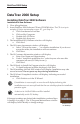
DataTrac 2000 Setup DataTrac 2000 Setup Installing DataTrac 2000 Software Installation of New Software 1. Close all applications. 2. Insert DataTrac 2000 Software CD into CD-ROM drive. The CD is set up to autoplay. If it does not autoplay on your PC, go to Step 2a. a. Click Start button on tool bar. b. Click on My Computer. c. Double-click CD Drive. d. Double-click Setup.exe. 3. The InstallShield (IS) Welcome window will display. a. Click Next. 4. The IS License Agreement window will display. a.
DataTrac 2000 Setup Installation of Software Update (previous version exists on PC) 1. Close all applications. 2. Insert DataTrac Software CD into CD-ROM drive. The CD is set up to autoplay. If it does not autoplay on your PC, go to Step 2a. a. Click Start button on tool bar. b. Click on My Computer. c. Double-click CD Drive. d. Double-click Setup.exe. 3. The IS Welcome window will display. a. Click Next. 4. The IS Program Maintenance window will display.
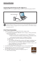
DataTrac 2000 Setup Connecting the Pump to a PC (Figure 1) USB port on PC: Use the supplied adapter cable to connect the pump to the PC. AirChek 2000 Model 210-2002 Serial No. 00000 U.S. Patent # 5,892,160 SKC Inc., Eighty Four, PA 15330 WARNING: Keep covers closed & do not connect to charger or data port in hazardous locations. Substitution of components may impair intrinsic safety.
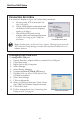
DataTrac 2000 Setup 5. If connection is successful, the AC 2000 Connection window will display a shaking hands icon (Figure 2A). Proceed to Step 6. If connection is unsuccessful, an error window will display (see box and Figure 2B on page 6). Figure 2. Connection window Figure 2A. Successful pump-PC communication Successive Connections 1. 2. 3. 4. 5. Connect the pump to a PC using the DataTrac adapter cable. Activate the pump LCD by pressing any button on the pump keypad.
DataTrac 2000 Setup Connection Error Box If an error box displays (Figure 2B), follow this procedure: a. Ensure pump LCD is activated. See Step 2 on page 4. b. Check cable/adapter connections and click Retry. If the error box displays again, go to Step c. c. Ensure the COM ports for the adapter cable are numbered between Figure 2B. 1 and 9. See changing the COM Port Connection error box box below. Note: Another option in the error box is Ignore.
DataTrac 2000 Setup 6. If the date and time settings on the PC and pump differ by a day or more than 5 minutes, respectively, a Time Discrepancy Alert window will display (Figure 3). a. Reconcile the date and time. b. If you select “Set my pump to the time of the computer,” a window will appear warning that the pump time cannot be changed unless pump history is cleared (Figure 3A). i. Select Yes if you wish pump history to be cleared and the time on the pump to be changed to the time on the PC. ii.
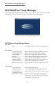
SKC DataTrac Pump Manager SKC DataTrac Pump Manager The SKC DataTrac Pump Manager window (Figure 4) is the first window that opens in DataTrac 2000. All windows are accessible from this main window. Figure 4. SKC DataTrac Pump Manager Window SKC DataTrac Pump Manager Menus File Menu Exit.................................exits the program and returns to Windows View Menu Pump Scheduler ..........opens the SKC Pump Scheduler window STEL/Timed Run .........opens the STEL/Timed Run window Sample Sheet .......
SKC DataTrac Pump Manager About Menu .......................................displays the DataTrac Software version, pump firmware revision, pump serial number, build number, and date of last calibration CalChek Note: If using pump version 2.59 to 2.61 without the CalChek feature, the date of manufacturer calibration will appear and remain in the About menu. If using pump version 2.59 to 2.61 with the CalChek feature, the date of last full calibration will appear in the About menu.
SKC Real Time Monitor Window SKC Real Time Monitor Window The SKC Real Time Monitor window (Figure 5) directly controls the connected pump, allows calibration of the flow, displays a real time readout of the pump operations, and provides the connected pump‘s serial number. H B C D A F E G Figure 5. Real Time Monitor Window A. B. C. D. E. F. G. H.
SKC Real Time Monitor Window Real Time Monitor Display The Real Time Monitor display (Figure 6) shows the operating status of the connected AirChek 2000/3000 pump. Figure 6. Real Time Monitor Display Monitor Display Cell Readout Pump Status .........................FLOW: Pump in Run mode HOLD: Pump in Hold mode FAULT: Pump in Flow Fault mode PROG (HOLD): Pump program in memory, pump in Hold mode Flow.......................................current flow rate in mL/min Volume ................................
SKC Real Time Monitor Window Flow Calibrate The Flow Calibrate buttons (Figure 7) allow the flow rate displayed on the connected pump LCD to be calibrated to the flow rate displayed on a primary standard calibrator. Click here to increase the pump flow rate. Click here to decrease the pump flow rate. The Approx Correction (approximate correction) is the difference between the flow rate displayed on the pump and the flow rate displayed on the calibrator.
SKC Real Time Monitor Window disconnect the interface cable from the pump, and insert the cable plug into the interface port on another AirChek 2000 pump. Once all pumps are set up, click the Multiple Pumps checkbox to deselect this option. You will be returned to the Real Time Monitor window. Using Flow Calibrate 1. Set the pump to the desired flow rate. 2. Connect the inlet port of the pump to a primary standard calibrator and read the flow on the calibrator. 3.
SKC Real Time Monitor Window Pressure Display The Pressure Display (Figure 9) shows the atmospheric pressure of the air entering the connected pump. Pressure Display Cell Readout Min ........................................................minimum atmospheric pressure during the run Max ........................................................maximum atmospheric pressure during the run TWA.......................................................time-weighted average of all atmospheric pressure Ambient ........
SKC Real Time Monitor Window Units Selection Buttons The Units Selection buttons (Figure 11) select the temperature and pressure scale of the connected pump. Units Selection Function Fahrenheit ........................................selects the Fahrenheit temperature scale Celsius...............................................selects the Celsius temperature scale in-Hg .................................................selects the inches Hg pressure units scale millibars ....................................
SKC Real Time Monitor Window Set Date/Time for Pump The Set Date/Time for Pump window (Figure 13) found in the Tools menu is the interface that allows the pump’s date and time to be set by clicking the various buttons. Figure 13. Set Date/Time for Pump Window Buttons Function Set & Exit ..............................saves the current time and date settings in pump memory and returns to the Real Time Monitor Exit (No Set) .........................
STEL/Timed Run Window STEL/Timed Run Window The STEL/Timed Run window (Figure 14) is used to set the sample time function (S┌) of the connected pump. Figure 14. STEL/Timed Run Window STEL/Timed Run Menus File Menu Exit.............................exits the STEL/Timed Run window Tools Menu Clear STEL in Pump ....................cancels the pump’s sample time period Change Default Flow Buttons ............
SKC Pump Scheduler Window SKC Pump Scheduler Window The SKC Pump Scheduler window (Figure 15) is the DataTrac 2000’s programming window. From this window, programs can be created, uploaded to a connected pump, saved to a PC, downloaded from a pump to PC, and printed. B G A H F C I D E Figure 15. Pump Scheduler Window A. B. C. D. E. F. G. H. I.
SKC Pump Scheduler Window Pump Scheduler Menus File Menu Open ......................opens a pump program previously saved to a PC Save .......................saves a pump program to a PC Print ........................ prints the pump program schedule displayed on the screen Exit.........................exits the Pump Scheduler window View Menu History ..........................opens the SKC Pump History window Real Time Monitor ......opens the SKC Real Time Monitor window Scheduler Options .......
SKC Pump Scheduler Window Pump Program Scheduler The Pump Program Scheduler (Figure 17) contains a list of AirChek 2000/3000 programs (or Pump Program Schedules) set by the Program Edit Bar. The pump is programmed for a sampling operation by sending this list of programs to the pump memory. Figure 17.
SKC Pump Scheduler Window Cut Button To clear the selected (highlighted) program from the AirChek 2000/3000 Scheduler and place it into the Program Edit Bar, click on the Cut button (Figure 18). A program can also be cut by double-clicking the program number or the line number to the left of the rate column of the scheduler (Figure 16).
SKC Pump Scheduler Window Open Program To open a previously saved program, select the Open command from the File menu. Print Program To print the Pump Program Scheduler displayed on the screen, select the Print command from the File menu. New Value Button The New Value button (Figure 21) sets the flow rate of the pump. Button Function New Value ............................
SKC Pump Scheduler Window Clock The Clock (Figure 24) consists of a clock face, a digital display corresponding to the time on the clock face, AM and PM buttons, and the current date and time. Select the Start and Stop Times of the AirChek 2000/3000 programs by clicking on the perimeter of the clock face and on the AM or PM buttons. The clock face perimeter is divided into 10, 15, and 30-minute and 1-hour intervals depending on the selected clock resolution (Figure 26). Figure 24.
SKC Pump Scheduler Window Time Bump Buttons The Time Bump buttons (Figure 29) add or subtract the selected time interval to all program Start and Stop Times in the Pump Program Scheduler. Time Interval To select the time interval, click on a time interval button. Minus Button To subtract the interval to all programming steps, click on the - button. Plus Button Figure 29. Time Bump Buttons To add the interval to all programming steps, click on the + button.
SKC Pump Scheduler Window Date/Time Display To access the Date/Time Display window (Figure 32), go to the Tools menu in the SKC Pump Scheduler and select Compare Pump Clock/PC Clock. The Date/ Time Display window allows the PC and the connected pump time and date to be synchronized. Figure 32. Time Display Window Resetting the pump time to the PC time will result in the display of a Clear History Message (Figure 33). The pump history must be cleared before the pump time can be reset. Figure 33.
SKC Pump Program Settings Window SKC Pump Program Settings Window The SKC Pump Program Settings window (Figure 34) found in the SKC Pump Scheduler under the View menu and Scheduler Options selects the Run Time Options. The Run Time Options include User Lock Out, Temperature Units (Fahrenheit or Celsius), Pressure Units (inches Hg, millibars, or mm Hg), Reset Volume, Time, Temperatures, and Pressures, and Clear History.
SKC Pump Program Settings Window Buttons Functions User Lock Out ......................click on Yes to activate or No to deactivate; User Lock Out will prevent anyone from altering the pump operating parameters even if the security code is entered on the pump keypad. However, the operator will be able to scroll through the data display. Temp Units ...........................click to select Fahrenheit or Celsius scale. Pressure Units ......................
Sample Program Sample Program This sample program demonstrates step-by-step how to use the SKC Pump Scheduler window (see page 18) to set a program: A sampling operation requires the AirChek 2000/3000 pump to sample at a constant flow of 1000 mL/min from 8:00 AM to 4:00 PM daily for one work week. Enter the parameters as follows: Set the flow rate Click on the New Value button. The Scheduler Set Flow window opens. Click on the 1000 button then click on OK.
Sample Program Add extra days to the program schedule Click on the +Day button. This will add one day to the Start Date and Stop Date in the Program Edit Bar. Click on Insert to place the program into the Pump Program Scheduler. Repeat the procedure to add an additional day to the Pump Program Scheduler until each day of the week has been entered. Set the desired Run Time Options Select Pump Settings from the Options menu and click on the desired Run Time Options (see page 26).
SKC Pump History Window SKC Pump History Window The SKC Pump History window (Figure 35) displays a record of all operations performed or the history of the connected pump. Up to 40 histories can be stored in the pump memory. This window can also save to a PC or print the history. Figure 35. SKC Pump History Window SKC Pump History Menus File Menu Save ................................... saves a history file to a PC; view using ArchiveHistory Print ...................................
SKC Pump History Window Example of an AirChek 2000/3000 History File Printout: History Display The History Display (Figure 36) shows the record or history of all operations performed by the connected pump. A history will Figure 36. History Display remain on screen and in pump memory until it is cleared. If more than 40 history operations have occurred since history was cleared, they will roll over in memory so that the last 40 will be displayed.
SKC Pump History Window Timed Run ...................................... Pump running a preset sampling time (S┌ function) Sleep ................................................ pump in Sleep mode Pre-Cal Flow ................................... First calibration average, date, and time when using the single-point CalChek feature Post-Cal Flow.................................. Final calibration average, date, and time when using the single-point CalChek feature Parameter Value Flow Rate ..................
SKC Pump History Window Back Pressure Monitor Window The Back Pressure Monitor window (Figure 38) displays the accumulated back pressure data of the pump since the pump’s history was cleared. This window allows the user to view the back pressure data over a sample run, which can be an aid to determining if the pump has been tampered with. For example, if the back pressure suddenly drops, then later rises to normal, this could be an indication that the sample media was removed and replaced.
Archive History Window Archive History Window The Archive History window loads and displays an AirChek 2000/3000 history file saved to a PC. This window is empty until a history file (.hst) is opened. Archive History Menus File Menu Open ......................................opens a saved history file (.hst) Print .......................................prints the displayed history file Exit.........................................
Reports Reports DataTrac 2000 allows reports or worker exposure profiles to be printed or saved as text and imported into word processing software or a text editor. These files combine the setup data (information denoting sampling media, methods, location, etc.) from the Sample Sheet Setup window (Figure 39) and an AirChek 2000/3000 history (see pages 30-34). File menu Save as Text ..........................
Reports Setup Files The Sample Sheet Setup window contains a list of information (in data cells) that will be printed in a report. The Sample Sheet Setup window can be saved to a PC as a setup file (.stp). A setup file consists of all the information contained in all data cells. Enter Data into Sample Sheet To enter the information into the data cells, click on the cell then type the data using a keyboard. Save Setup To save all entered data, select the Save Setup command from the File menu.
Reports Worker Exposure Profile A worker exposure profile contains a setup file (sample sheet) and a pump history. A worker exposure profile can be created using the connected pump’s history or a history file saved to a PC. Worker Exposure Profile created with AirChek 2000/3000 History To create a worker exposure profile containing the sample sheet displayed on screen and the history of the connected pump, select the Merge Pump command from the Options menu.
Reports Example of an AirChek 2000/3000 Worker Exposure File Printout: Worker Exposure Profile File Name: c:\karin’s work folder\operating instrux\datatrac 2000\sample worker exposure profile.rpt Date Printed: Thu Sep 1, 2011 2:08:49 PM SN 36603 Min Temp 80.6F Max Temp 82.6F TWA Temp 81.
Reports CalChek Full Calibration Data Display and Verification Figure 41. Calibration Info Window Viewing CalChek Full Calibration Data Caution: Full calibration completely clears DataTrac 2000 pump history, run time parameters, and the Pump Scheduler. Full calibration data can be viewed and printed by going to the DataTrac Pump Manager window and clicking on the View menu. Choose Calibration Info. This will display calibration results, pump serial number, and date of the last full calibration.
Reports Validating CalChek Full Calibration Data To confirm printed calibration data, open the SKC DataTrac Pump Manager window and click on the View menu. Choose Calibration Info. Go to the Tools menu and choose Confirm Validation Code. Enter the calibration date shown on the printed report, enter each actual flow, and then enter the validation code. Click on the Check Validation Code button.
Transferring History Files Transferring History Files into Spreadsheets The AirChek 2000/3000 history files (.hst) can be transferred into a spreadsheet or other application. A typical AirChek 2000/3000 history file is shown below: AC2000/3000 HISTORY FILE 3280 SN 627 35898.637581 Min Temp 75.2F Max Temp 75.2F TWA Temp 75.2F Flow Correction Approximately -20 ml/min 9 8 257 0 35898.637245 1314 0 35898.637211 1282 0 35898.637176 258 2000 35898.637164 1 0 35898.637153 1025 0 35898.637106 261 0 35898.
Transferring History Files Decoding Pump Mode Fields The Pump Mode field must be converted to hexadecimal numbers. Many scientific calculators are capable of this conversion.
Transferring History Files Decoding Time Fields Time fields are based on a simple mathematical relationship. The number represents the time that has elapsed since midnight December 30, 1899, in days. For example: Time Value 0.25 0.75 1.5 365.25 35065.625 Represents Dec 30, 1899 Dec 30, 1899 Dec 31, 1899 Dec 30, 1900 Jan 1, 1996 6:00 AM 6:00 PM Noon 6:00 AM 3:00 PM The integer portion of the number represents the number of days that have elapsed since Dec 30, 1899.
Index Index - Button .............................................. 24 + Button ............................................. 24 +Day Button....................................... 20 About Menu ......................................... 9 Adapter Cable...................................... 4 AirChek 2000/3000 Serial Number.................................... 9 Software Version Number ................. 9 Time and Date (PC)........................... 7 Time and Date (pump).....................
Index Opening a Program ........................... 22 Pressure Ambient ........................................... 14 Max .................................................. 14 Min ................................................... 14 TWA................................................. 14 Pressure Display ............................... 14 Printing Programs ......................................... 22 Reports ............................................ 35 Sample Sheet Setup........................