Reading Device AS x70i DUO/IRRL AS x70i DUO/IRIR AS x70i DUO/KEY Manual and operational description
Manual and operational description Version January 2004 AS x70i DUO (all variants) SKIDATA AG Technical Documentation Untersbergstrasse 40 A-5083 Gartenau Telephone +43 6246 888-0, Telefax +43 6246 888-7 Internet http://www.skidata.com e-mail docu@skidata.com Copyright © 2004 by SKIDATA AG. All rights reserved. All information in the following document is protected by copyright law. No part of this document may be reproduced without the written consent of SKIDATA AG.
Manual and operational description AS x70i DUO (all variants) Note: In the US only the variants AS x70i DUO/KEY and AS x70i DUO/IRRL are sold and operated. Hence, only these two variants are FCC certified and the FCC rules are subject to these variants only. FCC 15.19: This device complies with Part 15 of the FCC Rules.
Manual and operational description AS x70i DUO (all variants) AS x70i DUO (all Variants) 1 Document Management – Version Table Tab. 1: Document Version Table for Installation & Maintenance Instructions Section Document Pages Version Date 1 16 1.
AS x70i DUO (all variants) 1 1 AS x70i DUO/IRRL AS x70i DUO/IRIR AS x70i DUO/KEY Version 1.
1 1.1 AS x70i DUO (all variants) Contents 1.1 Contents 1.1 Contents 1.2 1.2.1 1.2.1.
AS x70i DUO (all variants) 1 Safety Instructions 1.2 1.2 Safety Instructions All components of the AS x70i DUO (all variants) have been subjected to a series of safety tests. Any remaining dangers that may exist are pointed out during system training courses as well as in this manual and the installation guide. 1.2.1 General safety instructions and warnings System devices may be used exclusively for their intended purpose, as specified by the manufacturer.
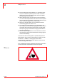
1 1.2 AS x70i DUO (all variants) Safety Instructions Persons affected by these guidelines (e.g. pacemaker wearers) are not allowed to place keycards or other contactless (electronic) access control data carriers next to the implant when passing an access device. When passing through an access gate, a minimum distance of 30 cm should be kept between the antenna and the implant (to ensure this minimum distance, the use of a Swatch Access watch or Gore [s-key] gloves is recommended).
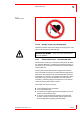
AS x70i DUO (all variants) 1 1.2 Safety Instructions Fig. 2: Prohibition label 1.2.1.2 Danger of injury by rotating parts Operators should be aware of the danger of bruising by the rotating worm drive inside Turnstile DKZ 350. DANGER OF INJURY – Never touch these parts while the unit is in operation. 1.2.2 Safety instructions – Turnstile DKZ 350 The DKZ 350 Turnstile unit is a machine as defined by EU Directive ‘98/37/EC Machinery’.
1 1.2 AS x70i DUO (all variants) Safety Instructions These instructions, particularly the safety instructions, must be followed by all operators responsible for maintaining and configuring the unit. Applicable local rules and regulations for accident prevention must be adhered to at all times. 1.2.2.1 Operating hazards of Turnstile 350 There is a theoretical risk of small children being hit in the back of the head by the automatically controlled turnstile bars.
AS x70i DUO (all variants) 1 Safety Instructions 1.2 safety regulations and instructions contained in this documentation; to ensure safety around the access area; to ensure that the required system maintenance tasks are carried out regularly. 1.2.2.4 Safety and warning devices The protection and warning devices to be installed around the danger area of the turnstile are to be kept in good condition. Warning signs and information posters are to be kept in readable condition. 1.2.2.
1 1.2 AS x70i DUO (all variants) Safety Instructions Disaster situations brought about by impact of foreign bodies or acts of God. 1.2.3 Electromagnetic Compatibility (EMC) All integral devices of Access Control System 350 have been developed, designed and manufactured in full compliance with EU Directive ‘89/336/EWG Electromagnetic Compatibility’. Compliance with EU Directive ‘89/336/EEC Electromagnetic Compatibility’ must be maintained during operation. This requires that Specified max.
AS x70i DUO (all variants) 1 1.3 Reading device AS x70i DUO 1.3 Reading device AS x70i DUO 1.3.1 Replacing the reader mechanism assembly Removing the reader mechanism assembly Using a 4 mm Allen wrench, unfasten and remove the fastening screw (Allen screw) at the rear of the reader. Press in the locking screw at the rear. Carefully tilt the top section towards the front, as indicated by the arrow in the illustration below.
1 1.3 AS x70i DUO (all variants) Reading device AS x70i DUO Fig. 4: Opening the reader top section Reinstalling the reader mechanism assembly Place the top section into the groove at the bottom of the front opening of the housing. Reconnect all cables, making sure they are completely inside the housing to avoid them being pinched. Push the mechanism assembly back into the housing. Fasten the Allen screw at the rear of the reader using a 4 mm Allen screw. Page 10 © SKIDATA AG, Version 1.
AS x70i DUO (all variants) 1 Reading device AS x70i DUO 1.3.1.1 1.3 Removing the protective hood of the reader mechanism assembly Press against the locking tab at the base of the hood (see illustration below: (2)). Remove the hood, bottom first (see illustration below: (2)). Fig. 5: Removing the protective hood of the reader mechanism assembly © SKIDATA AG, Version 1.
1 1.3 AS x70i DUO (all variants) Reading device AS x70i DUO 1.3.1.2 Removing the protective hood of the reader mechanism assembly (old version) Using a 2 mm Allen wrench, unfasten and remove the four Allen screws that hold the hood in place. Remove the hood. Fig. 6: Removing the protective hood of the reader mechanism assembly Page 12 © SKIDATA AG, Version 1.
AS x70i DUO (all variants) 1 Reading device AS x70i DUO 1.3.2 1.3 Cable connections inside the reader Fig. 7: Cable connections inside the reader © SKIDATA AG, Version 1.
1 1.3 AS x70i DUO (all variants) Reading device AS x70i DUO 1.3.3 Replacing traffic light lamps In the current production of the AS x70i DUO, LEDs are used for the traffic light. These LED lamps are maintenance free. Older versions of the AS x70i DUO use festoon bulbs. The replacing of the bulbs is described below. Fig. 8: Replacing traffic light lamps To ensure water tightness after replacing the lamp(s), the screw washers should be replaced with O-rings.
AS x70i DUO (all variants) 1 Reading device AS x70i DUO 1.3 The red/green traffic light is illuminated by special incandescent lamps. Spares are available from your SKIDATA™ service provider or from commercial hardware stores. Technical specifications: Festoon bulb, 24 V / 5 W, length: 37.5 mm Item code for red lamp: 470030050 Item code for green lamp: 470030052 1.3.
1 1.3 AS x70i DUO (all variants) Reading device AS x70i DUO 1.3.5 Replacing the Compact Flash card To replace the compact flash card, proceed as follows: Push the card ejection button (see illustration below). Take out the card. Insert the new card (ensure correct alignment). Fig. 9: Replacing the Compact Flash card Page 16 © SKIDATA AG, Version 1.