
Use and Care Manual


15
A p
10” Blade
Hoja Ø 254mm
Lame Ø 254mm
8
19
6
3
4
2
5
7
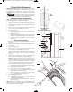
FIG. 20
FIG. 21
FIG. 22
17.
Adjustments
Adjusting 0° and 45° Positive Stops
Your saw is equipped with positive stops for fast and ac curate
positioning of the saw blade at 90° and 45° to the table.
To prevent personal injury, always dis con nect
plug from power source when making
adjustments.
1. Turn elevation wheel 2 clockwise and raise blade to maxi mum
height (Fig. 20).
Adjusting 0° Positive Stop:
2. Loosen the blade tilt lock handle 1 and push the elevation
wheel 2 to the left as far as possible and tighten the blade tilt
lock handle 1 (Fig. 20).
3. Place a combination square on the table with one end of
square against the blade as shown (Fig. 21), and check to see
if the blade is 90° to the table. If the blade is not 90° to the
table, loosen the blade tilt lock handle 1, loosen 90°
adjustment screw 4, loosen 90° bevel stop cam 5 and push
the elevation wheel until the blade is 90° to the table.
4. Tighten blade tilt lock handle 1, rotate the bevel stop cam 5
until it touches the bevel stop housing 7, then tighten 90°
adjustment screw 3.
5. Loosen adjustment screw 6 and adjust pointer 3 to indicate 0°
on the bevel scale.
Adjusting 45° Positive Stop:
6. Loosen the blade tilt lock handle 1 and push the elevation
wheel 2 to the right as far as possible and tighten the blade tilt
lock handle 1.
7. Place a combination square on the table with one end of
square against the blade as shown (Fig. 22), and check to see
if the blade is 45° to the table. If the blade is not 45° to the
table, loosen the blade tilt lock handle 1, loosen 45°
adjustment screw 8, loosen 45° bevel stop cam 9 and push
the elevation wheel until the blade is 45° to the table.
8. Tighten blade tilt lock handle 1, rotate the 45° bevel stop cam
9 until it touches the bevel stop housing 7, then tighten 45°
adjustment screw 8.
WARNING
!
SM 2610028628 01-13 E_SM 2610028628 01-13 E.qxp 1/11/13 2:46 PM Page 17