
Use and Care Manual


10
Assembly
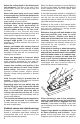
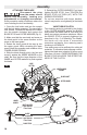
ATTACHING THE BLADE
Disconnect the plug
from the power source
before any assembly, making any
adjustments or changing accessories.
Such preventive safety measures reduce the
risk of starting the tool accidentally.
1. Press the lock button and turn the wrench
until the lock button engages. The saw shaft is
now locked. Continue to depress the button,
turn the wrench clockwise and remove the
BLADE STUD and OUTER WASHER (Fig. 2).
2. Make sure that the saw teeth and arrow on
the blade point in the same direction as the
arrow on the lower guard.
3. Retract the lower guard all the way up into
the upper guard. While retracting the lower
guard, check the operation and condition of the
LOWER GUARD SPRING.
4. Slide the blade through slot in the foot and
mount it against the INNER WASHER on the
shaft. Be sure that the large diameter of the
INNER and OUTER washers lay ush against
the blade.
5. Reinstall the OUTER WASHER. First nger
tighten BLADE STUD, then TIGHTEN the
BLADE STUD 1/8 TURN (45˚) WITH THE
WRENCH PROVIDED.
Do not use wrenches with longer handles,
since it may lead to over tightening of the blade
stud.
VARI-TORQUE CLUTCH
This clutching action is provided by the friction
of the OUTER WASHER against the BLADE
and permits the blade shaft to turn when the
blade encounters excessive resistance. When
the BLADE STUD is properly tightened (as
described in No. 5 of Attaching The Blade),
the blade will slip when it encounters
ex cessive resistance, thus reducing saw’s
tendency to KICKBACK.
One setting may not be sufcient for cutting all
materials. If excessive blade slippage occurs,
tighten the blade stud a fraction of a turn more
(less than 1/8 turn). OVERTIGHTENING THE
BLADE STUD NULLIFIES THE EFFECTIVE-
NESS OF THE CLUTCH.
FIG. 2
Tighten
Loosen
LOWER GUARD
SPRING
LOWER
GUARD
BLADE SHAFT
UPPER GUARD
LOCK
BUTTON
BLADE STUD
OUTER WASHER
Large Diameter
Faces Blade
BLADE
INNER WASHER
Large Diameter
Faces Blade