
Use and Care Manual


13
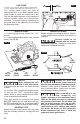
PLUNGE CUTS
Disconnect the plug from the power source
before making adjustments. Set depth
adjustment according to material to be cut.
Reconnect the plug to the power source.
Hold the main handle of the saw with one
hand, tilt saw forward and rest front of the foot
plate on material to be cut. Line up the cutting
guide notch with the line you’ve drawn. Raise
the lower guard using lower guard lift lever
and hold the front of the foot plate with the
other hand. (Fig. 9).
Position the saw with the blade just clearing
the material to be cut. Start the motor and
once it has reached full speed, gradually lower
the back end of saw using the front end of the
foot as the hinge point.
Once the foot plate rests at on the surface
being cut, release the lower guard and move
the hand holding the front of the foot plate to
hold the auxiliary handle. Proceed cutting in
forward direction to end of cut.
Allow the blade to come
to a complete stop
before lifting the saw from the cut. Also,
never pull the saw backward, since the
blade will climb out of the material and
KICKBACK will occur. Turn the saw
around and finish the cut in the normal
manner, sawing forward. If corners of your
plunge cut are not completely cut through,
use a jigsaw or hand saw to finish the
corners.
FIG. 9
FOOT
LOWER
GUARD LIFT
LEVER
LINE GUIDE
To resume cutting after cutting is interrupted,
squeeze the trigger and allow the blade to
reach full speed, re-enter the cut slowly and
resume cutting.
When cutting across the grain, the bers of
the wood have a ten den cy to tear and lift.
Advancing the saw slowly minimizes this
effect. For a nished cut, a cross cut blade or
miter blade is rec om mended.
CUTTING MASONRY/METAL
This tool is not designed for use with metal or
masonry cut-off wheels.
Do not use abrasive
wheels with circular
saws. Abrasive dust may cause lower
guard to not operate properly.
CUTTING LARGE SHEETS
Large sheets and long boards sag or bend,
depending on support. If you attempt to cut
without leveling and properly supporting the
piece, the blade will tend to bind, causing
KICK-BACK and extra load on the motor (Fig.
10).
WRONG
FIG. 10