
Install Instructions


Page 11
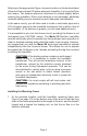
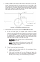
Remove the frame and drill the remaining mounting holes 7/64" (0.28
cm) in diameter. Drill a 3/8" (0.95 cm) diameter hole within the center
section, and cut and remove the rectangular section as previously
marked.
NOTE: When mounting Model 55, an additional notch is
required as shown in Figure 10 (page 10). Measure and
mark as indicated, and cut out this section.
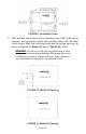
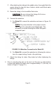
Using #8 sheet metal screws, attach the mounting frame to the duct,
as shown in Figures 9, 10 and 11 (page 10). Make sure the air ows
in the direction indicated.
Installing the Humidier Pan (Model 55)
Attach the humidier housing (i.e., the pan) to the mounting frame by
inserting hinge pins into the mated hinge halves.
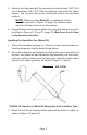
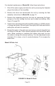
Place the evaporator pad between the two guide rails in the bottom of
the pan, then place the pad frame/drip tray assembly over the evapo-
rator pad, with the rubber grommet facing you. Insert the rubber water
tube into the rubber grommet, as shown in Figure 12, below.
3.
4.
1.
2.
AIR FLOW
FIGURE 12: Insertion of Model 55 Evaporator Pad and Water Tube
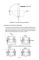
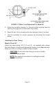
Raise the unit into a closed position and securely fasten in place, as
shown in Figure 13 (page 12).
3.