Anakin Club Racer ENGLISH
INTRODUCTION CONGRATULATIONS on your purchase of a SKY-HERO Anakin Club Racer, we hope that it will provide you with many years of fun and entertainment. SKY-HERO products are designed and developed in Belgium (Europe), but distributed and supported across the globe through a network of dealers and outlets that can provide assistance and advice.
GENERAL INSTRUCTIONS AND GUIDELINES FOR USE • The aircraft should not be flown by children and definitely not by anyone under the age of 14. • Failure to follow and comply with the safety advice and recommendations in this manual, can result in serious injury to you, others or property. • You should always check the local laws and regulations of the country where you will operate the aircraft, to ensure you are in compliance with them.
TABLE OF CONTENTS PARTS LISTING 5 ADDITIONAL ITEMS REQUIRED TO COMPLETE 7 REQUIRED TOOLS AND EQUIPMENT 7 MAIN FRAME - ASSEMBLING THE ARMS 8 ROUTING OF MOTOR CABLES 8 FIXING THE MOTORS TO THE FRAME 9 SOLDERING THE MOTORS TO THE ESCS 9 PDB CONNECTIONS 14 CAMERA SETUP 16 CHANGING YOUR VTX OUTPUT POWER 18 PAIRING YOUR SKY-HERO LINK9 RADIO AND TRANSMITTER 19 CC3D FLIGHT CONTROLLER SETUP USING OPEN PILOT GCS SOFTWARE 20 TRANSMITTER SETUP WIZARD 26
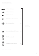
PARTS LISTING ISO7380 M3X14MM ISO7380 M3X10MM 2X 20X ISO7380 M3X6MM 6X SELF TAPPING SCREW M3X6MM 4X DIN 9021WASHER M3 6X Screwset SKH07-112 SKH54-02-SCREW INSERT ANAKIN 6X FRONT MAIN SPACER 2X MIDDLE-REAR MAIN SPACER 4X Note: - screws 1/1 scale 5
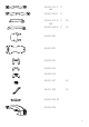
SKH03-215-F 5" OR SKH03-260-F 6" SKH03-215-R 5" 2X OR SKH03-260-R 6" 2X SKH03-201 SKH03-201 SKH03-201 SKH03-015 SKH03-015 SKH01-107 4X SKH01-104 2X SKH05-024-01 SKH05-026 SAUF INDICATION CONTRAIRE: LES COTES SONT EN MILLIMETRES ETAT DE SURFACE: TOLERANCES: LINEAIRES: ANGULAIRES: NOM CASSER LES ANGLES VIFS FINITION: SIGNATURE DATE NE PAS CHANGER L'ECHELLE REVISION TITRE: AUTEUR VERIF. APPR. FAB. MATERIAU: QUAL.
ADDITIONAL ITEMS REQUIRED TO COMPLETE (with our recommendations) Radio Transmitter & Receiver • Link9 Mode 1 Radio & Receiver - SKH02-001-M1 • Link9 Mode 2 Radio & Receiver - SKH02-001 Power Distribution Board • PDB + 5V BEC - SKH04-026 Motors (quantity x4) • X-NOVA 2204 (for 5" Anakin Club Racer) - SKH04-028 • X-NOVA 2206 (for 6" Anakin Club Racer) - SKH04-022 Esc’s • Littlebee 12-20A (2-4S) - SKH04-025 3-4S Lipo Battery and a Battery retaining strap • Anakin Lipo 3S 1300mAh 35C – SKH08-012
MAIN FRAME - ASSEMBLING THE ARMS M3X16mm MIDDLE FRAME SPACER FRONT FRAME SPACER A ROUTING OF MOTOR CABLES DÉTAIL A ECHELLE 2 : 1 8
FIXING THE MOTORS TO THE FRAME TIP: When attaching the motors to the frame, make sure you do not accidentally pinch the motor cables. It may be easier to secure the motors on the frame first, before running each set of motor cables through the cable protector cap SOLDERING THE MOTORS TO THE ESCS Position the ESCs on the underside of the Arms leaving 10mm space between the edge of the ESC and main body of the Club Racer.
PRO TIP: If you have a way to determine each motors direction of rotation correctly (with its associated ESC); confirming the correct ESC-to-Motor wiring at this point, can save you some time later in the build process.
The power and signal cables coming from the ESCs should be routed through the vertical posts of the centre frame as shown below You should use 12AWG cable for the battery power lead. All cables should be soldered so that their cables go from the edge of the PDB inwards towards the centre (for the battery cable, this avoids that the battery pushes against its soldered PDB connection, when being put in place).
- + - + BATTERY CONNECTION (2-4S) USE SOLDERING IRON, TO CONNECT CABLES TO POWER DIST. BOARD + + - (SUITABLE FOR POWERING CC3D FLIGHT CONTROLLER) - 5V FILTERED OUT PUT BATTERY VOLTAGE OUT (2-4S) (SAME VOLTAGE AS BATTERY - MAY BE SUITABLE TO POWER YOUR VTX, CHECK YOUR VTX VOLTAGE REQUIREMENTS) Note: the output labelled “Camera” provides the same voltage as your battery input.
You can now stick the PDB in place using double sided adhesive tape, making sure that you align the PDB with the edge of the frame.
PDB CONNECTIONS - + + + - (SUITABLE FOR POWERING CC3D FLIGHT CONTROLLER) + 5V FILTERED OUT PUT - BATTERY CONNECTION (2-4S) BATTERY VOLTAGE OUT (2-4S) (SAME VOLTAGE AS BATTERY - MAY BE SUITABLE TO POWER YOUR VTX, CHECK YOUR VTX VOLTAGE REQUIREMENTS) NOTE: the output labelled “Camera” provides the same voltage as your battery input.
Pass the 3 cables up from lower part of the frame to the top of the frame. The Yellow video out cable can then be soldered or connected to the VTX video input cable.
CAMERA SETUP In order to make fine adjustments to your camera angle, it may be necessary to slightly ream out (deepen the size of) the grooves in the adjustable lower camera plate (this can be done using a small file or drill) ° 45 30° 37,5° 45° NOTE: You can remove the camera at any point to adjust its position by slightly unscrewing the two bolts holding the curved bracket above the camera Using double sided adhesive tape, position the CC3D flight controller in the middle of the upper frame and 10m
Next step is to use double sided adhesive tape to position the Link9 Radio Receiver behind the CC3D Flight Controller as shown in diagram below. The SBus Port is horizontal port in bottom right corner of the image below and left to right the pins are; signal, positive and negative.
CHANGING YOUR VTX OUTPUT POWER FROM 25mW – 200mW The Sky-Hero VTX is cable of operating in 2 power modes, either 25mW or 200mW. By default the output power is set to 25mW, but to increase it to 200mW you need to cut the small wire shown in the 2 images below.
PAIRING YOUR SKY-HERO LINK9 RADIO AND TRANSMITTER Ensure that you have removed your propellers and that your VTX antenna is in place. Switch on your Link9 Radio (if you already have another aircraft setup on your Radio, you may need to select a new model within the Transmitter menu).
CC3D FLIGHT CONTROLLER SETUP USING OPEN PILOT GCS SOFTWARE WARNING! Make sure you have removed your propellers before starting this section! This instruction is for setting up the CC3D flight controller that comes with your Club Racer ARF with the Link9 Radio/Receiver and using the OpenPilot GCS software for the Microsoft Windows platform. If you are not using the Sky-Hero Link 9 radio with its receiver go to page 28 Ensure that you downloaded and installed a copy of the OpenPilot GCS v15.05.
2. Click the Vehicle Setup Wizard 3. On the Vehicle Setup Wizard welcome screen, Click Next 4. On the Firmware update screen, remove the tick from “Erase all settings” option and Click the “Upgrade” button 5.
6. On the Board Identification screen, Click Next 7. On the Input signal configuration screen, Select the SBus Option and Click Next 8. On the Vehicle type selection screen, ensure that “Multirotor” is selected and Click Next 9. On the Multirotor configuration screen, ensure that “Quadcopter X” is selected and click Next 10. On the Output signal configuration screen, ensure that “Oneshot 125” is selected and Click Next 11.
12. On the Sensor Calibration Procedure Screen, ensure that the CC3D is on a flat level surface, where it will not be subject to any movement or vibration, then Click “Calculate” (and ensure the CC3D is not moved until the calibration process is completed), then Click Next 13. On the ESC Calibration Procedure Screen, double check that your battery is not connected and no propellers are attached, then tick the 3 boxes and Click Start 14.
15. On the Output Calibration Screen, Click Next and connect your Lipo battery 16. To find the neutral rate (slowest smooth rotation speed) of each motor, Click “Start” and then move the slider to the right until the motor starts to turn, adjust the slider left or right until you reach the slowest speed at which the motor’s rotation is smooth and constant. Check that the motor’s direction of movement (clockwise or anti-clockwise) matches the image shown in the OpenPilot Calibration Screen.
19. On the Configuration ready to save screen, Click Save, then Click Finish. NOTE: If any of your motors were not turning correctly (in the Output Calibration part of the setup process earlier), then Exit the OpenPilot Software, disconnect your Lipo battery from the Club Racer and disconnect the usb cable from the CC3D, then move the Heat shrink tubing (for the affected motor) along the wires so that you have access to the ESC and then un-solder any 2 (of the 3) wires going between the motor and the ESC.
TRANSMITTER SETUP WIZARD Now it’s time to calibrate the radio. Turn your radio transmitter on, ensure that you do not have your propellers attached to the Anakin Club Racer and then connect the Lipo Battery. - If your computer is still connected via the usb lead to the CC3D then go to step 2 below - If your micro usb lead is not already connected between the CC3D’s usb port and your computer – you should ensure that the Open Pilot software is not running, and then re-connect it the usb lead.
5.
8. When the screen below appears, center your control sticks, then Click Next 9. The final step in the Wizard process is to click on the Arming Settings Tab at the top of the screen and decide on the method you would like to use “Arm” the Club Racer. The Arming process is designed to help avoid that your Club Racer’s motors start turning by accident. NOTE: the Throttle stick must always be at its lowest position in order for the arming process to work.
TESTING YOUR ANAKIN CLUB RACER ARMING PROCESS WORKS Ensure that your propellers are not yet connected to your Anakin Club Racer, Insert your Battery into the battery bay and secure tightly with a strap. Turn on your Radio Transmitter. Make sure that your Anakin Club Racer is in a safe position with nothing close by that could be damaged when you start the motors.
MANUALLY RE-CALIBRATING YOUR ESCS 1. Ensure that propellers are not attached and that your Anakin Club Racer is in a safe position where spinning the motors will not cause any danger 2. Ensure that the OpenPilot software is not running on your computer, connect the USB cable between the CC3D and your computer, wait a few moments for your computer to recognise the connection and then open the OpenPilot software.
7. Click the “Test Outputs” box (to remove the tick from it) and acknowledge the message about saving neutral settings. Remove the battery, Click the Save button and then re-connect the battery Click the “Test Outputs” box (to put the tick back in it) and once again acknowledge the message about saving neutral settings. 9. Remove the tick out of Test Outputs (all motors will stop) Acknowledge the message about saving your Neutral settings and Click Save 8.
ATTACH YOUR PROPELLERS Complete the build by attaching your propellers in accordance with the image below, paying special attention to the writing on the propellers – the letter “R” after the size (e.g. 5 x 4.5R), indicates that the propeller is a ClockWise (CW) turning propeller. If you do not have an “R” after the number this means it is a CounterClockWise (CCW) turning propeller.
Your final setup should look like the image below, and you just need to fix your canopy in place CC3D BATTERY STRAP RX VTX LIPO BATTERY (2-4S) 33
SELECTING YOUR FLIGHT MODE VIA SWITCH “C” FLIGHT MODE (C SWITCH) 1. Stabilized Super Soft 2. Stabilized Soft 3. Rate 1. STABILIZED SUPER SOFT: (ATTITUDE MODE) Switch C in UP position • Club Racer comes back to a level position when RIGHT STICK is back to neutral position – • The maximum angle of the aircraft is VERY LIMITED. 2.
BEFORE YOU TAKE OFF Refer to and follow all safety precautions mentioned in the “General Instructions and Guidelines for use” section of this manual. Check that your aircraft is ready for flight with no loose screws or fittings (pay special attention to the propellers) insert a battery into the battery bay and use the provided strap to secure the battery in place.
USING ALTERNATIVE RADIOS & RECEIVERS (not the SKY-HERO Link9) SKY-HERO CC3D FLIGHT CONTROLLER IS ONLY COMPATIBLE WITH: • S-BUS receivers • JR & Spektrum Satellite receivers • PPM receivers Please note that PWM (Pulse With Modulation) is NOT SUPPORTED! During the CC3D setup process, you will be asked to choose the receiver type from four options, please choose your receiver according to the box above, (but do not choose PWM as this is not compatible with the Anakin Club Racer ESCs) if you make the
DSM/SPEKTRUM/JR (SATELLITE CONNECTION) Another receiver option is the Spektrum/JR Satellite. It allows a Spektrum/JR or satellite receiver to be connected to the CC3D. For JR/Spektrum/DSM satellite receiver, plug the signal wire on the satellite to the DSM port on the main board. Then swap the ORANGE and BLACK wire at any end of the plug. (see explanation on next page) DSM2/DSMX satellite receiver signal wire swap For DSM/Spektrum/JR please use black, red, white cable.
LIMITED WARRANTY WARRANTY AND REPAIRS Warranty requests will be processed only with an original proof of purchase from an authorized SKY-HERO dealer, showing the name of the buyer as well as the date of purchase. If the case for Warranty is confirmed, the product will be repaired. Only SKY-HERO will be able to take the decision about repairing the product. SKY-HERO will only accept a return under warranty in case of evident product failures.
QUESTIONS, ASSISTANCE AND REPAIRS Without consulting SKY-HERO directly, your local dealer or point of sale can perform an estimate as to your eligibility for repair under our Warranty. Please, in such a case, contact your dealer who will agree with SKY-HERO of an appropriate decision, to assist you as soon as possible. REPAIRS UNDER WARRANTY If your product requires maintenance or repair, please contact either your dealer or SKY-HERO directly. Package the product carefully.