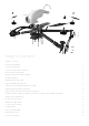
Assembly Instruction Manual 2015.
TABLE OF CONTENT SCREWS 1/1 SCALE 1 GLUE THE TUBES END’S 2 ATTACH YOUR MOTORS 3 ATTACH MOTOR MOUNTS ON ARMS 4 ROUTE YOUR MOTOR CABLES 5 FIX YOUR SIDE FRAME USING 2 SCREWS 5 SOLDER YOUR ESC’S 6 SLIDE ESC’S INTO THE TUBES 7 PRESS THE INSERTS IN POSITION 8 SLIDE YOUR FRAME SPACER AROUND THE TUBES 9 CHOOSE THE POSITION OF YOUR ARMS 10 SLIDE YOUR MOTOR SHAFTS INTO THE MOUNTING JIG 11 SOLDER YOUR ESC CABLES, EQUIPEMENTS CABLES TO YOUR BATTERY CONNECTOR CABLES 12 SCRE
SCREWS 1/1 SCALE ISO 7380 M3X6 ISO 7380 M3X4 ISO 7380 M3X6TP ISO 7380 M3X8TP ISO 7380 M3X30 DIN 912 M2.5X8 HEX NUT M2.
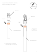
GLUE THE TUBES END’S (Wipe out excess of glue with acetone) USE 5MIN EPOXY GLUE SKH01-106-F SKH01-106-R USE EPOXY GLUE * USE EPOXY GLUE 8MM * 8MM FIG.
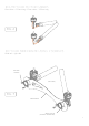
ATTACH YOUR MOTORS Warning! Before starting: - Make sure to identify your clockwise (CW) and counter-clockwise (CCW) motors*. - Be aware that all your wires will go backwards as shown in figure 3 SKH04-009 SKH01-105 FIG. 2 ISO 7380 M3X6 CCW CW FIG.
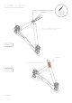
Pay attention to motor support orientation. (See figure 4) You must build 1CW+1CCW with the motors’s wires oriented to the side of the nut for Anakin’s front side and 1CW+1CCW with the motors’s wires oriented to the side of the screw for Anakin’s rear side FIG. 4 BUILD 1CW+1CCW FOR REAR SIDE BUILD 1CW+1CCW FOR FRONT SIDE ATTACH MOTOR MOUNTS ON ARMS CW CCW CCW CW You must attach the motor mounts on arm’s ends until you hear a «clic» noise. it can require quite an important pressure FIG.
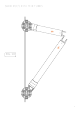
ROUTE YOUR MOTOR CABLES Rear cables = 220mm long / Front cables = 150mm long FIG. 6 FIX YOUR SIDE FRAME USING 2 SCREWS Build left + right side ISO 7380 M3x8TP (LEFT SIDE) FIG.
SOLDER YOUR ESC’S And check your motors direction SKH04-014* USE SOLDER & WELDING Let the esc outside the tube and connect it to check your motor rotation FIG. 8 SKH04-014* Use schrink tube to protect your esc’s FIG.
SLIDE ESC’S INTO THE TUBES FIG.
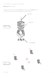
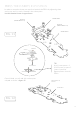
PRESS THE INSERTS IN POSITION In order to mount the frame you must first interlock the PEM’s by tightening them one by one until it’s totally inserted in the carbon plate. Use the threaded insert on upper frame. SKH03-200-S SH54-01 (FROM SKH07-111) SH54-03 (FROM SKH07-111) SKH03-200-U FIG. 11 THREADED SH54-03 NOT THREADED Once finished, you will end with carbon plate crimped as shown in figure 12 TIP: Use 1 frame spacer + 1 M3x30 screw, to press 2 inserts in position.
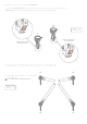
SLIDE YOUR FRAME SPACER AROUND THE TUBES (Use the threaded insert on upper frame) FIG. 13 FRONT SPACER REAR SPACER SKH01-103-F SKH01-103-R FIG.
CHOOSE THE POSITION OF YOUR ARMS ACCORDING THE CENTER OF GRAVITY ADJUSTMENT YOU WANT FRONT SPACER REAR SPACER SKH01-103-F SKH01-103-R FIG.
SLIDE YOUR MOTOR SHAFTS INTO THE MOUNTING JIG FIG.
SOLDER YOUR ESC CABLES, EQUIPEMENTS CABLES, ( VTX, UBEC, LED, ETC... ) TO YOUR BATTERY CONNECTOR CABLES EQUIPEMENTS FIG. 17 BATTERY CONNECTOR CABLES SCREW YOUR LOWER FRAME (DO NOT OVERTIGHT) ISO7380 M3X30 TIP: PEM’s are already pressed in position (see figure 11) SKH03-200-L SKH03-200-L (FROM SKH07-111) FIG.
FIX YOUR MOTOR MOUNT FIG.
SCREW THE THIRD SCREW FIG.
ATTACH YOUR Z SPACERS FIG. 21 SKH01-104 ISO7380 M3X6TP SKH01-109-00 ISO7380 M3X6 SKH04-109-00 FIG. 22 Fix your camera plate in position SKH01-108-00 FIG.
CAMERA ANGLE YOU CAN ADJUST THE ANGLE OF THE CAMERA AS FOLLOWED FIG. 24 * Standard setup FIG. 25 * 20 ° FIG.
ADJUST MOTORS ANGLE To adjust motor angle to banked position, you need to untight the plactic ring or alu ring on the side and tilt The motor mounts until the edge of the sideframes*. *You need optional sideframes in order to do this. Check accessories in the Anakin section of our website (www.sky-hero.com) to order them or run to the closest Sky-Hero dealer! 0° Standard setup FIG. 27 10° Banked setup FIG.
EQUIPMENTS LAYOUT * * SKH04-10 (CC3D) YOUR VIDEO TRANSMITTER FIG.
ATTACH YOUR CANOPY FIG.