INSTRUCTION MANUAL EQ8 Mount 100113V1 Copyright © Sky-Watcher
CONTENT PART I : SETTING UP THE EQ8 MOUNT 1.1 Setting Up the Tripod ...............................................................................................3 1.2 Putting On the EQ8 Mount .......................................................................................5 1.3 Installing the Counterweights ..................................................................................6 1.4 Installing the Telescope ..................................................................................
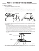
PART I : SETTING UP THE EQ8 MOUNT 1.1 Setting Up the Tripod 1. Fully expand the tripod legs on level ground. 2. Install the hand control bracket on the tripod. (Fig 1.1a) 3. Place one or two counterweight(s) just between the bottom of the central post and the ground if there is enough space between them. This is a critical safety effort because the counter weight(s) will prevent users from putting their feet under the central post unconsciously. (Fig. 1.1b) Hand Control Bracket M3X10 Screws Fig. 1.1a Fig.
PART I: SETTING UP THE EQ8 MOUNT 5. Assemble the 3 adjustable spider trusses as shown in Fig 1.1d and Fig 1.1e. Do not tighten the thumb screws at this moment. Thumb Screw Spider Truss See Fig. 1.4 Fig. 1.1e Fig. 1.1d 6. Slide the central post up/down in the clamp (Fig. 1.1c) to the proper height and then tighten the 3 thumb screws on the spider trusses to prevent the central post from falling. 7. Tighten both hex nuts on the clamp to secure the central post in the clamp.
PART I: SETTING UP THE EQ8 MOUNT 1.2 Putting On the EQ8 Mount 1. Loosen the two azimuth adjustment knobs on the EQ8 mount until there is sufficient space between the two knob screws (Fig. 1.2a). Remove the two azimuth locking screws and washers on the tripod top. 2. Align the metal dowel on the tripod top with the gap between the two azimuth adjustment knobs; and then put the mount on the tripod top. (Fig 1.2b) Azimuth Locking Screw * Loosen * Azimuth Adjustment Knobs * Dowel Loosen Fig. 1.2a Fig. 1.
PART I: SETTING UP THE EQ8 MOUNT 6. Slide the jackscrew handle in the hole at the end of the jackscrew shaft. Apply two ball head screws on the handle. (Fig. 1.2d) Ball-head Screw Jackscrew Shaft Counterweight Shaft Fig. 1.2d 1.3 Installing the Counterweights 1. Screw the counterweight rod into the mount as shown in Fig. 1.3a. 2. Remove the stopper cap at the end of the counterweight rod. 3. Loosen the counterweight’s thumb screw and slide the counterweight onto the counterweight rod.
PART I: SETTING UP THE EQ8 MOUNT 2. Release the Dec. clutch knob (Fig 1.4) and rotate the Dec. axis until the three knobs on the saddle are facing upward and the dovetail groove is leveled (Fig 1.4). Tighten the Dec. clutch again. Arrow Sign Saddle Dec. Clutch R.A. Clutch Fig. 1.4 3. Loosen the three knobs on the saddle alternately until the width of groove is slightly wider than the width of the dovetail bar on the telescope. 4.
PART II : POLAR ALIGNMENT Prior to operating the EQ8 mount, it must be polar-aligned. 2.1 Prepare the Mount for Polar Alignment 1. Set up the EQ8 mount, counterweights, and telescope as described in PART I. It is recommended to polar-align the EQ8 mount with all equipments installed. 2. Loosen the primary locking knob and both azimuth locking screws; and then use the azimuth adjustment knobs to put the azimuth locking screws to the middle of the slots (Fig 2.1a).
PART II: POLAR ALIGNMENT 2.2 Polar Alignment Using the SynScan Hand Controller 1. Choose 2-Star alignment or 3-Star alignment to align the mount, and then perform the polar-alignment routine. Repeat these operations several times until the SynScan hand controller reports small polar alignment error after the 2-Star alignment or 3-Star alignment. Refer to SynScan hand controller’s manual for detail operation instruction. 2.
PART II: POLAR ALIGNMENT Fig. 2.3b • For observing in Northern Hemisphere: Find the Polaris (The brightest star near the North Celestial Pole) in the polar scope; then use the jackscrew and the two azimuth adjustment knobs to move the Polaris to the proper position in the FOV of the polar scope. (Refer to the upcoming section “The Orientation of Polaris in Polar Scope”).
PART II: POLAR ALIGNMENT 2.4 The Orientation of the Polaris in Polar Scope As the Polaris is not located exactly at the North Celestial Pole, we can see it orbits the North Celestial Pole in a polar scope. The large circle seen in the center of the pattern in Fig. 2.3b is a representation of the Polaris’ orbit around the North Celestial Pole. When performing the polar alignment process, it is necessary to determine the orientation of the Polaris on the circle.
PART II: POLAR ALIGNMENT 2.5 Align the Polar Scope Before using the polar scope for polar alignment, the polar scope itself must be calibrated to ensure the pattern in the polar scope is aligned to the mount’s R.A. axis. This includes two calibration routines: Routine 1 - Align the pattern plate to the rotating axis of the polar scope 1.
PART II: POLAR ALIGNMENT Note: • When adjusting the Allen screws, loosen one screw only ¼ of a turn, and then tighten the other two. • Do not over tighten the Allen screws; it might damage the pattern plate in the polar scope. • Do not loosen one screw completely or loosen more than one screw at a time; otherwise, the pattern plate in the polar scope will be disengaged and further adjustment is impossible.
PART III : ELECTRONIC CONTROL INTERFACE 3.1 Control Panel The control panel of the EQ8 Mount is shown below: Fig. 3.1 3.2 Panel Interface Components: POWER: This is an outlet from which the mount and the hand control get power supply. To connect to a power supply, align the index on both the plug of the cord and the outlet on the panel, and then insert the plug to the outlet. Tighten the knurled cap on the plug to secure the plug on the panel.
PART III: ELECTRONIC CONTROL INTERFACE 4. Intermittent one flash: The PPEC training routine has been triggered, but the controller in the mount has not received the worm index signal and the correction-recoding has not started yet. 5. Intermittent two flashes: The PPEC training routine has been started and the controller in the mount has received the worm index signal and started to record the PE correction. When the intermittent two flashes stops, it means the PPEC training has finished. 6.
PART IV : OTHER EQ8 MOUNT FEATURES 4.1 Freedom FindTM Function The EQ8 mount is equipped with auxiliary encoders on both the R.A. axis and Dec. axis. Therefore, the mount can keep tracking its current position even when a user unlocks the clutches and rotates the mount in R.A. axis and Dec. axis manually. With this feature, a user can manually operate the mount anytime without worrying about losing the mount’s alignment status.
APPENDIX I : SPECIFICATIONS Dimensions: Ø180 Ø140 473 45° 800~1100 360 894 272 Mount 2-Ø 6 76 Ø 124 M12 Tripod 4-M 6 54 Mount 76 100 160 Mount Bottom Plate Saddle Head 17
APPENDIX I : SPECIFICATIONS Specifications: Product Name EQ8 Mount Mount Type German Equatorial Mount Payload (Counterweights excluded) 50kg Latitude Adjustment Range 10º to 65º Azimuth Adjustment Range ±10 º Weight (Tripod excluded) 25 kg Counterweight 2 x 10kg/ea Tripod 29.4kg Counterweight Rod 2.6kg Power Requirement DC11~16V 4A Motor 0.9 º Hybrid Stepper Motor Transmission 435:1 Worm Drive + 64 Micro-step/0.9º Stepper Motor Drive Gear Ratio 435 Resolution 11136000 Counts/Rev.
EQ8 Mount
EQ8 Mount Packing List EQ8 Mount x 1 Instruction Manual x 2 6 mm Allen Wrench x 1 INSTRUCTION MANUAL EQ8 Mount INSTRUCTION MANUAL SynScan AZ-EQ6 GT Mount TM Mount Package Includes: 100113V1 Copyright © Sky-Watcher 021112V1 Copyright © Sky-Watcher Counterweight Shaft x 1 Jackscrew Handle x 1 Power Cable Clamp x 1 SynScan Hand Control V3 x 1 Power Cable x 1 PC-Link Cable x 1 Shutter Release Cable (for Canon EOS) x 1 SynScan Hand Control Cable x 1 Counterweight x 2 Wrench x 1 Adjustable Stan