INSTRUCTION MANUAL SynScan TM 140303V4 Copyright © Sky-Watcher
Basic Operations CONTENT PART VIII : AUXILIARY FUNCTIONS PART I : INTRODUCTION 1.1 1.2 1.3 1.4 Outline and Interface .......................................................................................... 4 Connecting to a Telescope Mount ...................................................................... 4 Slew the Mount with the Direction Keys .............................................................. 4 SynScan Hand control’s Operating Modes ...................................................
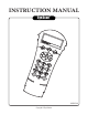
PART I : INTRODUCTION PART I: INTRODUCTION • 1.1 Outline and Interface A SynScan hand control and its interfaces are shown in Fig. 1.1 LCD Display Screen: It can display two lines of text, 18 characters per line. The contrast and the brightness of the red backlight are adjustable. • • The left and right keys are used to control the movements of the Right Ascension (R.A.) axis (for an equatorial mount) or the azimuth axis (for an Alt-azimuth mount).
PART II : INITIALIZATION PART I: INTRODUCTION In Full Feature mode, the hand control must connect to a Sky-Watcher telescope mount. After turning on the power to the mount, the hand control must complete an “Initialization” routine, followed by an “Alignment” routine which establishes a model to transform the coordinates of the mount and the coordinates of the sky. Only after the “Alignment” is done can the SynScan hand control’s high precsion “GOTO” function be used to locate a celestial object.
PART II: INITIALIZATION PART II: INITIALIZATION 3. Warning Message Confirmation The hand control will display a warning message about the dangers of viewing the sun with a telescope. • Press ENTER to confirm you have read the warning messages and proceed to the next step. Press ESC to return to the previous (firmware version display) step. • Users can slew the mount with direction keys in this step. 4.
PART III : ALIGNMENT 3.1 Choosing an Alignment Method At the beginning of the alignment process, users are asked to choose an alignment method. The available alignment methods differ between the mount types, as listed below: • For an equatorial mount: 1-Start Alignment (1-Star Align.), 2-Star Alignment (2-Star Align.) or 3-Star Alignment (3-Star Align.) • For an alt-azimuth mount: Brightest Star Alignment (Brightest Star) or 2-Star Alignment (2-Star Align.
PART III : ALIGNMENT PART III : ALIGNMENT 4. Now the screen will display “Point scope to RR ZZ.Z’ TT.T’ ”, which means point the telescope to RR region, the exact azimuth is ZZ.Z degree and the exact altitude is TT.T degree. Users can use the direction keys on the SynScan hand control to move the mount and point the telescope to the 1st alignment star selected in the previous step.
PART III : ALIGNMENT PART III : ALIGNMENT 3.5 Alt-Azimuth Mounts using 2-Star Alignment Method Aligning the 1st Star: 1. The LCD screen displays “Choose 1st Star” in the first line. Use the scrolling keys to browse through a list of star names and Press ENTER key to pick the one on the screen as the 1st alignment star. 2. Now the screen will display “Point scope to ZZZ zz.z’ sTT tt.t’ ”, which means point the telescope to the direction whose azimuth is ZZZ degree, zz.
PART IV : SYNSCAN MENU TREE PART III : ALIGNMENT 2. Equatorial Mount with 2-Star Alignment: Advantage: For visual observing, the mount does not need to be polar-aligned accurately. Preconditions: Small cone error in the telescope-mount setup. Rules for choosing alignment stars: • The deviation in R.A. of the two alignment stars should not be too small or too close to 12 hours; the recommended deviation is between 3 hours and 9 hours.
PART V : LOCATING OBJECTS PART IV: SYNSCAN MENU TREE 4.2 Accessing Menus The SynScan hand control’s menu is only accessible after the initialization, or after the star alignment routine is completed (If it is chosen to start). Users can use the ESC key, the ENTER key, and the two scrolling keys to access the menu.
PART V : LOCATING OBJECTS PART V : LOCATING OBJECTS 5.2 Locating NGC and IC Objects 5.5 Locating SAO Stars The process for locating NGC or IC objects is similar to that for locating Messier objects (Section 5.1), with the following differences: • Press the “NGC” shortcut key to access the NGC catalog. The screen will display “NGC Catalog / NGC =”. The NGC catalog index number ranges from 1 to 7840. • Press the “IC” shortcut key to access the IC catalog. The screen will display “IC Catalog / IC =”.
PART V : LOCATING OBJECTS PART V : LOCATING OBJECTS • 3. Locate the Object: • The operation is similar to that of locating Messier objects; refer to Section 5.1 for details. 5.7 Deep Sky Tour The SynScan hand control can generate a list of the most famous deep sky objects which appear in the current sky. Users can pick them one by one and the SynScan hand control can point the telescope to them for observing automatically. This is the “Deep Sky Tour” function. • 3.
PART VI : CONFIGURE THE TELESCOPE MOUNT 6.1 Choosing Tracking Speed • 1. Access the menu “SETUP\Tracking” and press the ENTER key. 2. Use the scroll keys to browse through the following options, and press the ENTER key to pick one. • • • • • PART VI : CONFIGURE THE TELESCOPE MOUNT Sidereal Rate: Enables the mount to track celestial objects at the sidereal rate for ob- serving the stars, deep sky objects, and planets. Lunar Rate: Enables the mount to track at the lunar rate for observing the Moon.
PART VII : CONFIGURE THE HAND CONTROL 7.1 Display and Keypad 8.1 Editing Date, Time, Coordinates, Time Zones, and Daylight Saving Time 1. Access the menu “Setup \ Handset Setting” and press the ENTER key. 2. Use the scroll keys to select “LCD Contrast”; then use the left/right direction keys to adjust the contrast of the LCD screen. 3. Use the scroll keys to select “LED Backlight”; then use the left/right direction keys to adjust the brightness of the keypad’s LED backlight. 4.
PART VIII : AUXILIARY FUNCTIONS • • • • • PART VIII : AUXILIARY FUNCTIONS H.C. Firmware: The firmware version of the SynScan hand control. Database: The database version of the SynScan hand control H.C. Hardware: The hardware version of the SynScan hand control. Motor Controller: The firmware version of the motor controller of the mount. H.C. Serial #: The serial number of the SynScan hand control. 8.
PART IX : CONNECTING TO A COMPUTER 10.1 Hardware Requirements 9.1 Working with Astronomical Applications After the SynScan hand control is initialized, it can communicate with a computer via the RS232C connection on its multi-purpose port. The computer must have a RS-232C serial port; otherwise, a USB-to-Serial adapter is required. Connect the SynScan hand control and the serial port with the PC-Link cable (the RJ-12 to D-Sub 9 cable) which comes with the telescope mount.
PART XI : ADVANCED FUNCTIONS PART X : UPDATING FIRMWARE • Check the “Auto-detect COM port” to let the application detect the proper serial port that will connect to the SynScan hand control. Clear it to manually choose the COM Port and select a serial port from the “COM port” drop-down list. • Click the “HC Version” button to check the versions of the hardware, firmware, and database. • Click the “Update” button to start loading the firmware to the SynScan hand control. 4.
PART XI : ADVANCED FUNCTIONS PART XI : ADVANCED FUNCTIONS The SynScan hand control divides the sky into 85 small zones, and users can calibrate the pointing error for each of these zones. The next time that the SynScan controller tries to locate an object in the calibrated zone (or a zone nearby), it will automatically apply the recorded calibration data to compensate the pointing error.
PART XI : ADVANCED FUNCTIONS • • • • PART XI : ADVANCED FUNCTIONS The initial polar alignment should not be too far off to avoid the polar alignment error in azimuth exceeding the adjustment range of the mount. It is necessary to use a reticle eyepiece in the 2-Star alignment, 3-star alignment and polar alignment process. Generally, the cone error in a telescope-mount setup might reduce the accuracy of this polar alignment process.
PART XI : ADVANCED FUNCTIONS PART XI : ADVANCED FUNCTIONS 11.5 Periodic Error Correction (PEC) for EQ Mount The periodic error correction function applies to an equatorial mount only. All equatorial mount has periodic tracking error which is not critical for visual observing but might lower the picture quality of long exposure astrophotography. The SynScan hand control has the periodic error correction (PEC) function to improve the tracking performance for astrophotography.
PART XII : USING A SYNSCAN GPS MODULE APPENDIX I : ELIMINATING CONE ERROR Users may purchase a SynScan GPS module to acquire accurate local geographical coordinates and local time; it will help improve the accuracy of the mount alignment and the polar alignment. If the telescope’s optical axis is not perpendicular to the declination axis of the equatorial mount, then there is cone error in the telescope-mount system.
APPENDIX II : SYNSCAN SELF-DIAGNOSIS APPENDIX III : SCHEMATIC OF THE PORTS The SynScan hand control contains a built-in self-diagnosis program. To run a full test, users should prepare a “Loop-Test Plug” by referring to Appendix 3 and the following instructions: • Vpp+ RX(RS232C) COMMON GND TX(RS232C) SHUTTER Short the pin-2 (TX_RS232C) and pin-5 (RX_RS232C) of a RJ-12 plug. Here are the diagnosis steps: 1. Insert the “Loop-Test Plug” to the RJ-12 port of the SynScan hand control. 2.
SynScan TM