www.skylinkhome.com Total Protection Alarm System MODEL: SC-1000W If you would like to order Skylink’s products or have difficulty getting them to work or download information and user manual, please : 1. visit our FAQ website at www.skylinkhome.com, or 2. email us at support@skylinkhome.com, or 3. call our toll free at 1-800-304-1187 from Monday to Friday, 9 am to 5 pm EST.
SKYLINK TECHNOLOGIES INC. TABLE OF CONTENTS Your Guide to this manual includes SC100 – The Alarm System and AD105 – The Emergency Dialer Total Protection Alarm System PACKAGE CONTENTS...................................................................................................... 4 OVERVIEW........................................................................................................................... 5 PLANNING YOUR HOME SECURITY NEEDS.....................................................
PACKAGE CONTENTS Everything required for installation is included with this package 1 Control 1 1 1 OVERVIEW Congratulations! You have just purchased one of the most reliable and up-to-date wireless security systems on the market today. Skylink is the first company to incorporate the rolling code technology in a home/business security system. This innovative technology provides increased security and trouble free wireless connections which greatly reduces false alarms.
PLANNING YOUR HOME SECURITY NEEDS INSTALLATION Before you begin to install your security system, analyze the premises to determine your security needs. Consider those doors and windows which are more likely to be used as points of entry by an intruder, the ones that are poorly lit or the entrances that can not be seen from the street. The Control Panel, door/window sensors and the motion sensor are installed using the screws included.
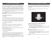
INSTALLATION INSTALLATION 4. Attach the unit to the wall. If hanging the unit, insert two screws using the template provided. If screwing the back directly to the wall, take the back plate right off by prying apart one hinge. Use as much force as needed. The plastic hinge will not break. 2. Position the magnetic switch connected to the transmitter on the door/window frame. 3. Position the magnet on the door beside the magnetic switch. They should be no more than 1 cm (3/8 inch) apart.
INSTALLATION TESTING YOUR SYSTEM WALK TEST Before you learn how to use your security system, test to make sure that the door/ window sensors and the motion sensor are communicating with the Control Panel. After mounting the sensor at the desired location, it is important to perform a walk test in order to determine if the sensor is detecting the things you want to detect. Set the Control Panel to CHIME MODE which will emit a subtly two tone chime when any of the sensors are activated.
LIGHTS AND SOUNDS Below is an explanation of the lights and sounds of the Control Panel. LIGHTS ACPWR light on ACPWR light off LOBATT. light off LOBATT. light flashing ARM light off ARM light on System is being powered by electrical current. System is not receiving any electrical power. Backup battery is connected and working. Backup battery is weak, needs to be replaced. System is disarmed. System is armed.
STANDARD PROGRAMMING KEYCHAIN TRANSMITTER (4B-434) You hear a long beep. The arm light and the red lights in zones 3 and 4 go on. Both the green and red lights flash in zone 1 for 45 seconds which gives you 45 seconds to leave the premises before the system is activated. After 45 seconds, both the green and red lights in zone 1 remain on. Upon re-entering the premises through zone 1, you have 30 seconds till the alarm sounds.
KEYCHAIN TRANSMITTER (4B-434) TO DISARM THE SYSTEM, OR DEACTIVATE THE SIREN USING THE KEYCHAIN TRANSMITTER When the system is armed: Press button #3. The red light on the transmitter flashes and the Control Panel beeps twice. The system is now disarmed. PASSWORDS MASTER PERSONAL IDENTIFICATION NUMBER (MPIN) Security access to the SC-100 is controlled by a MASTER PERSONAL IDENTIFICATION NUMBER (MPIN) or SECONDARY PERSONAL IDENTIFICATION NUMBER (SPIN).
PASSWORDS ADVANCED PROGRAMMING SECONDARY PERSONAL IDENTIFICATION NUMBER (SPIN) PROGRAM SENSORS TO DIFFERENT ZONES You may want to give someone limited access to the system, (baby sitter, cleaner, repairman etc.). For this purpose the SC-100 provides you with the option of adding up to 3 separate SPIN. You now have a basic understanding of how the SC-100 security system works.
ADVANCED PROGRAMMING ADVANCED PROGRAMMING To program sensors to send their signals to a different zone, you must first clear them from communicating with their current zone. 4. Press the number key to identify which zone to add the Motion Sensor to [1, 2, 3 or 4]. We recommend you program the motion sensor to zone 2. The zone light will flash for eight seconds. TO CLEAR A ZONE 5. While the zone light is flashing, press [ * ]. 1. Enter the current MPIN. 2. Press [ B ]. 3.
ADVANCED PROGRAMMING STANDARD ARMING SEQUENCES Each zone can be programmed to react 5 different ways when it receives a signal from a remote sensor. 1. Chime Mode - represented by the green lights When only the green light is on and the Control Panel receives a signal from a remote sensor, the Control Panel emits a subtly two tone chime. ADVANCED PROGRAMMING premises without activating the alarm. Zone 2 (the motion sensor), is off allowing movement in the premises and zones 3 & 4 are instant.
SUMMARY OF ARMING SEQUENCES Below is a table summarizing all the preprogrammed sequences. Sequence Zone 1 MPIN A # chime MPIN B C exit delay (after 45 sec.)entry delay Zone 2 Zones 3 & 4 When sequence should be used FOR TESTING chime chime use for testing after installation and to test batteries, also use as a subtle chime when a remote sensor has been activated BASIC PROGRAMMING off instant use when leaving the premises entry delay instant and no one is inside MPIN C exit delay (after 45 sec.
BATTERY MAINTENANCE BATTERY MAINTENANCE MOTION SENSOR BATTERY DOOR/WINDOW SENSOR BATTERY The Motion Sensor operates on a 9 volt alkaline battery accessible beneath a sliding panel on the bottom of the unit. All remote sensors come with the battery. Disarm the Control Panel before replacing all batteries. Each door/window sensor operates on a 12 volt alkaline battery that is inside the transmitter. The sensors come with the batteries already installed.
ADDITIONAL ACCESSORIES Additional sensors and transmitters as well as add on accessories are available to work with your security system.
ADDITIONAL ACCESSORIES Audio Sensor (AS-433) - Detects alarm sound from existing security system alarm; sends signal to Dial-Alert. - Eliminates need for monitoring service. - 9V alkaline battery included Temperature Sensor (TS-101A) - Monitors temperature of a specific area (i.e., greenhouse, horse farms, laboratory etc.
TABLE OF CONTENTS INSTALLATION WARNING NOTICE...........................................................................33 PACKAGE CONTENTS..........................................................................................34 OVERVIEW..................................................................................................35-36 INSTALLATION............................................................................................................37-39 LIGHTS AND SOUNDS.........................
PACKAGE CONTENTS All materials required for installation are included with this package 1 1 1 1 1 Dial-Alert (AD-105) Telephone Line antenna (installed) AC adapter 9 volt alkaline battery OVERVIEW The AD-105 emergency dialer can call multiple phone numbers during an emergency situation and it will playback prerecorded messages. There are 2 operating modes you can set up in the AD-105 dialer.
OVERVIEW Dial Alert AD-105 must work with the specific sensors listed below. Ensure only the listed sensors are used with the AD-105, otherwise, the communication between the sensors and the Dial Alert may not function properly. If you have a Skylink wireless device or sensor that is not listed below, and uncertain whether it can work with your AD-105, please contact our customer support team.
INSTALLATION 2. Thread the telephone line through the top hole in the back of the unit and plug it into the "LINE" jack. If you want to have an answering machine on the same line as the dialer, thread the phone line through the bottom hole in the back of the unit and plug it into the "PHONE" jack of the dialer. The phone line(s) must be inserted through the back of the unit before it is attached to the wall. 3.
LIGHTS AND SOUNDS STANDARD PROGRAMMING Below is an explanation of the lights and sounds of the Dial-Alert LIGHTS ACPWR light on ACPWR light off LOBATT. light off LOBATT. light on ARM light on ARM light off Keypad backlight dialer is being powered by AC adapter. dialer is not receiving any AC power. backup battery is connected and working. backup battery is weak, battery needs to be replaced. the dialer is in armed condition.
STANDARD PROGRAMMING RECORD A VOICE MESSAGE You must record a message and program at least one phone number in order for the Dial Alert to work. The voice recording procedure is different between the 2 operating modes, SC-001 Mode and Sensor Mode. To record a voice message under SC-001 Mode: 1. Enter the current password (factory default password is 0000), then press [PROG], display will show [P] meaning you are now in programming mode. 2. Enter [3] which represents voice recording. You will see [P3 0 40].
STANDARD PROGRAMMING STANDARD PROGRAMMING Do not program the phone number to police or fire dept directly into your Dial-Alert unless you have checked with your local authorities. Please also inform all the recipients that their phone numbers have been programmed into your dialer, so they know exactly what happens when they receive your emergency message. 1. Enter the current password (factory default password is 0000), then press [PROG], display will show [P] meaning you are now in programming mode. 2.
OPERATIONS SC-001 Mode When the display shows “rEAdy”, that means the unit is in standby mode. It will dial when it receives a panic signal from the alarm panel, or its own panic button is pressed. It will dial the programmed phone numbers and playback the voice message. It is not necessary to put the AD-105 in arm mode. Once the display shows “rEAdy”, the AD-105 will respond if it receives a command to dial out.
ADVANCED PROGRAMMING ADVANCED PROGRAMMING Changing Password Erase Programmed Panic Transmitters / Alarm Panels / Sensors Password is required for programming purposes. Factory default is 0000. To change the setting, follow the instructions below. You may erase the programmed wireless devices, panic transmitter, alarm panels and wireless sensors. You cannot erase a specific device, you must erase all the devices and then program the ones that you would like to keep. 1.
ADVANCED PROGRAMMING 3. Enter [1] to disable universal dial tone meaning a proper dial tone must be presented before dialing, or [2] to enable universal dial tone, so the Dial Alert will dial regardless of the dial tone. 4. If the new setting is accepted, it will emit 2 beeps. If you don’t hear 2 beeps, that means the setting is not accepted, retry again. Pick up Pause Period Pick up Pause allows you to have a pause period after the recipient picks up the call.
ADVANCED PROGRAMMING BATTERY MAINTENANCE CONNECT THE DIAL-ALERT WITH YOUR EXISTING ALARM SYSTEM You may connect your existing alarm system with the Dial-Alert so that the dialer will be triggered by your alarm system when it is activated. There are 2 ways you can connect your dialer with your existing alarm system. 1. Connect the dialer with the alarm system using hard wire (normally closed). 2. Connect the dialer with the alarm system using the Audio Sensor (AS-101). PANEL OR SENSOR N.C..
ADDITIONAL ACCESSORIES Additional sensors and transmitters as well as add on accessories are available to work with your Dial-Alert.
ADDITIONAL ACCESSORIES Audio Sensor (AS-101) - Detects alarm sound from existing security system alarm; sends signal to Dial-Alert. - Eliminates need for monitoring service.