Quickstart Guide for v4 Hub Installations CHANGELOG Date Version Author(s) 20200311 0.
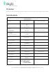
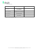
Overview Welcome to Skylo! This document provides a brief overview how to get up and running with a Skylo Hub. Specifications V4 Hub Specifications Dimensions 212 x 212 x 43 mm Weights Hub MMP Harness w/M12 Connector Power Requirements Power-on Operating (average) Transmitting (peak) Power Sources Internal Battery External via M12 Connector When secured to MMP 920 g 200 g 100 g/m (typical) 12 W max. 2.5 W max.
L-Band Spectrum: 34MHz Wi-Fi: ~20dbm EIRP BLE: ~13dbm EIRP SAT NB: 40dbm EIRP RF Output Power Emission and Bandwidth RHCP (Right Hand Circular Polarisation) Product Purpose/Class Hours of Operation NB ioT Satellite Modem 24 hours/365days Specifications are subject to change without notice. SKYLO TECHNOLOGIES | 268 Lambert Ave., Palo Alto, CA 94306 | WWW.SKYLO.
Related Documents Additional, detailed information can be found in the following Skylo documents: ● ● Reference User Guide for v4 Hub Installations Mobile Application User Guide -- Android SKYLO TECHNOLOGIES | 268 Lambert Ave., Palo Alto, CA 94306 | WWW.SKYLO.
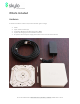
What’s Included Hardware A Hub kit’s hardware consists of (CW from bottom right in image): ● ● ● ● ● A Hub A pair of Hub release keys A matching Multifunction Mounting Plate (MMP) A power & charging harness with M12 connector An optional external power supply that mates to the free end of the harness SKYLO TECHNOLOGIES | 268 Lambert Ave., Palo Alto, CA 94306 | WWW.SKYLO.
Software Obtain and install the Skylo mobile application on your mobile phone. Setting Up the Hub Locating and Installing the Hub Follow these steps to setup Hub to connect to the Skylo network. See the images in Appendix A for installation and removal. 1. Make note of the Hub’s identifying information label (with MAC ID, etc.) should you require it at a later stage when onboarding the Hub. 2. Identify an outdoor location, with a clear view of the sky. 3. Choose a location for the hub.
Onboarding the Hub onto the Skylo Network Follow the steps in the Skylo Mobile Application User Guide -- Android for onboarding. SKYLO TECHNOLOGIES | 268 Lambert Ave., Palo Alto, CA 94306 | WWW.SKYLO.
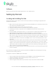
Appendix A - Installation & Removal Images MMP with alignment arrow and release key slots In this image, the MMP has been secured to an aluminum plate that has four M6 stainless-steel studs in it. Four M6 self-locking nuts in the corners of the MPP secure it to the aluminum plate. The MMP is rigidly and permanently secured to the aluminum plate, and is now ready to have a Hub installed onto it. MMP secured to aluminum plate with studs via M6 locknuts.
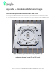
Aligning the Hub with the MMP A Hub can be installed onto an MMP in any one of four orientations, via the mating bayonets of the Hub and MMP. The start location for the bayonet is ⅛ of a turn counterclockwise (CCW) from having the sides of the Hub aligned with the sides of the MMP. When the correct Hub-MMP orientation is achieved, the Hub will drop down into the MMP by 6mm. Hub inserted on top of MMP SKYLO TECHNOLOGIES | 268 Lambert Ave., Palo Alto, CA 94306 | WWW.SKYLO.
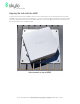
Locking the Hub into position on the MMP Once the Hub is aligned with the MMP and dropped down into it, turn the hub clockwise (CW) by ⅛ of a turn until a positive click is heard and felt. This locks the Hub to the MMP securely. Hub locked into place on MMP SKYLO TECHNOLOGIES | 268 Lambert Ave., Palo Alto, CA 94306 | WWW.SKYLO.
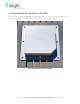
Unlocking the Hub from the MMP To separate a Hub from an MPP, it must first be unlocked. Insert two Hub release keys 180 degrees apart where the padlock icon is visible on a bare MPP. One of two Hub release key slots between the Hub and the MMP. An optional security screw can be used to prevent unlocking. SKYLO TECHNOLOGIES | 268 Lambert Ave., Palo Alto, CA 94306 | WWW.SKYLO.
Insert each key fully. The Skylo logo on each Hub release key must be visible: Hub release keys installed between Hub and MMP. Hub can now be rotated CCW to release it from the MMP. SKYLO TECHNOLOGIES | 268 Lambert Ave., Palo Alto, CA 94306 | WWW.SKYLO.
With the keys fully inserted, rotate the Hub 1/16 of a turn counterclockwise (CW), to the stop: Limit of unlocking rotation when Hub release keys are in place. Once the limit of unlocking rotation with the Hub release keys still in place has been reached, remove the Hub release keys and continue rotating counterclockwise (CCW) until the stop. Then remove the Hub from the MMP. Store the Hub release keys in a safe location. SKYLO TECHNOLOGIES | 268 Lambert Ave., Palo Alto, CA 94306 | WWW.SKYLO.
M12 Harness mating to Hub The M12 harness screws onto the Hub’s M12 connector to form a rainproof, sealed connection to the Hub. Always ensure that the keyed connector is aligned properly before screwing it fully onto the Hub’s M12 connector: M12 connector end of harness, fully engaged with Hub’s M12 connector. SKYLO TECHNOLOGIES | 268 Lambert Ave., Palo Alto, CA 94306 | WWW.SKYLO.
FCC PART 15 STATEMENT This device complies with Part 15 of the FCC Rules. Operation is subject to the following two conditions: (1) this device may not cause harmful interference, and (2) this device must accept any interference received, including interference that may cause undesired operation. This equipment has been verified to comply with the limits for a class A computing device, pursuant to FCC Rules.